00192169-01.pdf - 第41页
Order No. 00192 169-01 User Manual - Productivity Lift E_SPLFS03_V40_11_0300_200300_V1_14.doc Last update: 20.03.2000 - Version V 1.14 Page 41 7 Set-up mode In set-up mode, it is possible to enter and modify parameters t…
Order No. 00192 169-01 User Manual - Productivity Lift
E_SPLFS03_V40_11_0300_200300_V1_14.doc Last update: 20.03.2000 - Version V 1.14 Page 40
6.26 Start continuous mode 3
N.B.
This continuous operation mode can only be implemented by the manufacturer using special
test equipment. An attempt by a user to initiate this continuous operation mode produces an
error message.
Hand
Stop
Start
Enter
Alt
Figure 49: Start continuous mode 3
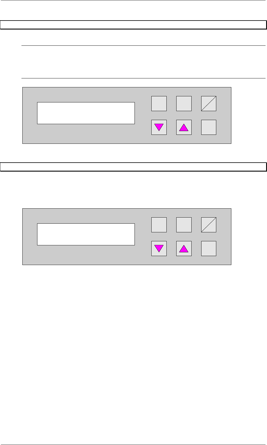
6.27 Input ident number
This feature enables the input of an identification number. The identification number allows to
define a variation of machine parameters for a specific PCB. This menu item allows to switch
on / off this function. The input has to be done in the set-up mode (section 7.1, page 41)
Hand
Stop
Start
Enter
Alt
Figure 50: Input ident number
Start continuous
mode 3?
Input ident no.
Turned off
Order No. 00192 169-01 User Manual - Productivity Lift
E_SPLFS03_V40_11_0300_200300_V1_14.doc Last update: 20.03.2000 - Version V 1.14 Page 41
7 Set-up mode
In set-up mode, it is possible to enter and modify parameters that do not serve the basic
setting of the system, but that, for example, show the values dependent on the size of the
machine type. Press the Alt key to access the set-up mode menu.
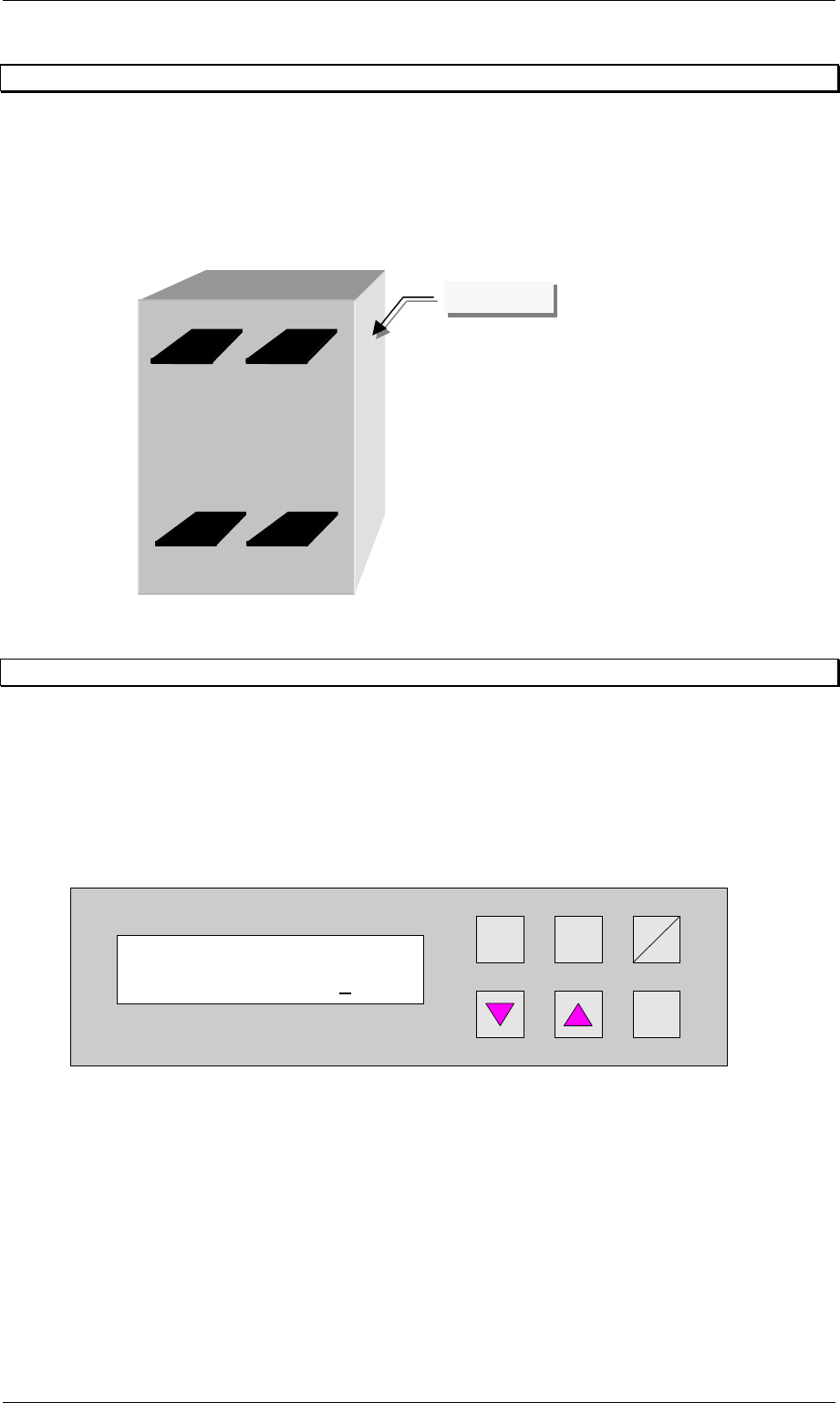
Definition:
View of the direction of transit.
Figure 51: Definition / schematic of the transport tracks
7.1 Ident number
This selection can be used to assign an identification number to the following set of
parameters. When starting the system, only the corresponding PCB number need be called
up, and the system sets the stored parameters automatically. The number consists of two
assignment digits and one eight-digit identification. The assignment digits can be used to call
up the parameter set when starting the system. The eight-digit identification can be changed at
random and only serves the input of user-specific identification numbers. Each number has
only one numerical entry.
Hand
Stop
Start
Enter
Alt
Figure 52: Ident number
Ident number
01 00000001
Track 1Track 2
Track 3Track 4
Operator side

Order No. 00192 169-01 User Manual - Productivity Lift
E_SPLFS03_V40_11_0300_200300_V1_14.doc Last update: 20.03.2000 - Version V 1.14 Page 42
7.2 Machine type
Here, the type of system is determined, which corresponds to the position and mode of
operation of the device thus required in the production line.
The following types of machine are defined for the Productivity Lift:
Input module : If the lift is at the beginning of the Siplace assembly line, this setting must be
selected in machine type. The input module can only transfer printed circuit
boards on transport tracks 1 and 2. Priority is given to attempting to then
transfer the PCBs to the placement machine. If this is not possible, the
unassembled PCBs are forwarded essentially to track 3 on the lower level
and then transported for the time being to the next lift (intermediate module)
or the placement machine.
Cluster module : The intermediate module is located after the input module and is defined as
the intermediate module as long as the subsequent placement machines are
of the same type. The intermediate module accepts either assembled PCBs
from tracks 1, 2 and 4, and transfers them further on track 4, or it accepts
unassembled PCBs from track 3 and attempts to deposit them at the
following placement machine. If the following placement machine is
occupied, the unassembled PCBs are transported further via track 3 to the
next lift or placement machine.
Allocation of the inlets and outlets to each other:
- take-over inlet track 1 → hand-over outlet track 4
- take-over inlet track 2 → hand-over outlet track 4
- take-over inlet track 3 → hand-over outlet track 1, 2 or 3
- take-over inlet track 4 → hand-over outlet track 4
In order to prevent the system becoming blocked, only one PCB may be
transferred if the allocated outlet is ready. Fixed priorities are allocated to the
individual transport directions. Inlet tracks 1 and 2 as well as outlet tracks 1
and 2 all have the same priority.
Otherwise the following applies:
1. take-over inlet track 3 → hand-over outlet tracks 1 and 2
2. take-over inlet tracks 1 and 2 → hand-over outlet track 4
3. take-over inlet track 3 → hand-over outlet track 3
4. take-over inlet track 4 → hand-over outlet track 4
Cross module : The setting cross module must always be selected if the type of placement
machine changes in the line. The cross module handles all incoming PCBs
as if they are unassembled. In this way, the PCBs arriving on tracks 1, 2 and
4 are presented to the placement machine for processing. If the following
placement machine is of the same type, PCBs can also be transferred on
track 3 at the cross module if the current placement machine is occupied. If
the cross module is the last lift before the final module, no PCBs may be
transferred on track 3. Similarly, no PCBs may be accepted from the last
intermediate module before this cross module.
Convert 4→2 : Convert module from 4 tracks to 2 tracks, whereby 4 tracks indicate the
lower and upper two tracks.
Application:
A suitable device should be used to break up a long placement line to allow
access for people, for example. This reduces the transport tracks to 2 tracks,
since a device can not have two tracks on the lower transport level. With the
convert module 4→2, PCB transport is reduced to 2 tracks, separated
according to assembled and unassembled PCBs.