00192169-01.pdf - 第43页
Order No. 00192 169-01 User Manual - Productivity Lift E_SPLFS03_V40_11_0300_200300_V1_14.doc Last update: 20.03.2000 - Version V 1.14 Page 43 Convert 2 → 4 : Convert module from 4 tracks to 2 tracks, whereby 4 tracks in…

Order No. 00192 169-01 User Manual - Productivity Lift
E_SPLFS03_V40_11_0300_200300_V1_14.doc Last update: 20.03.2000 - Version V 1.14 Page 42
7.2 Machine type
Here, the type of system is determined, which corresponds to the position and mode of
operation of the device thus required in the production line.
The following types of machine are defined for the Productivity Lift:
Input module : If the lift is at the beginning of the Siplace assembly line, this setting must be
selected in machine type. The input module can only transfer printed circuit
boards on transport tracks 1 and 2. Priority is given to attempting to then
transfer the PCBs to the placement machine. If this is not possible, the
unassembled PCBs are forwarded essentially to track 3 on the lower level
and then transported for the time being to the next lift (intermediate module)
or the placement machine.
Cluster module : The intermediate module is located after the input module and is defined as
the intermediate module as long as the subsequent placement machines are
of the same type. The intermediate module accepts either assembled PCBs
from tracks 1, 2 and 4, and transfers them further on track 4, or it accepts
unassembled PCBs from track 3 and attempts to deposit them at the
following placement machine. If the following placement machine is
occupied, the unassembled PCBs are transported further via track 3 to the
next lift or placement machine.
Allocation of the inlets and outlets to each other:
- take-over inlet track 1 → hand-over outlet track 4
- take-over inlet track 2 → hand-over outlet track 4
- take-over inlet track 3 → hand-over outlet track 1, 2 or 3
- take-over inlet track 4 → hand-over outlet track 4
In order to prevent the system becoming blocked, only one PCB may be
transferred if the allocated outlet is ready. Fixed priorities are allocated to the
individual transport directions. Inlet tracks 1 and 2 as well as outlet tracks 1
and 2 all have the same priority.
Otherwise the following applies:
1. take-over inlet track 3 → hand-over outlet tracks 1 and 2
2. take-over inlet tracks 1 and 2 → hand-over outlet track 4
3. take-over inlet track 3 → hand-over outlet track 3
4. take-over inlet track 4 → hand-over outlet track 4
Cross module : The setting cross module must always be selected if the type of placement
machine changes in the line. The cross module handles all incoming PCBs
as if they are unassembled. In this way, the PCBs arriving on tracks 1, 2 and
4 are presented to the placement machine for processing. If the following
placement machine is of the same type, PCBs can also be transferred on
track 3 at the cross module if the current placement machine is occupied. If
the cross module is the last lift before the final module, no PCBs may be
transferred on track 3. Similarly, no PCBs may be accepted from the last
intermediate module before this cross module.
Convert 4→2 : Convert module from 4 tracks to 2 tracks, whereby 4 tracks indicate the
lower and upper two tracks.
Application:
A suitable device should be used to break up a long placement line to allow
access for people, for example. This reduces the transport tracks to 2 tracks,
since a device can not have two tracks on the lower transport level. With the
convert module 4→2, PCB transport is reduced to 2 tracks, separated
according to assembled and unassembled PCBs.
Order No. 00192 169-01 User Manual - Productivity Lift
E_SPLFS03_V40_11_0300_200300_V1_14.doc Last update: 20.03.2000 - Version V 1.14 Page 43
Convert 2→4 : Convert module from 4 tracks to 2 tracks, whereby 4 tracks indicate the
lower and upper two tracks.
Application:
A suitable device should be used to break up a long placement line to allow
access for people, for example. This reduces the transport tracks to 2 tracks,
since a device can not have two tracks on the lower transport level. With the
convert module 2→4, PCB transport is increased again to 4 tracks,
separated according to assembled and unassembled PCBs, following this
type of interruption.
Output module : The final module is defined as the last lift in the direction of transit, after the
Siplace systems. Essentially, the final module has no lower belt. If the lift is
implemented as the final module, the abovementioned system types can not
be selected. The PCBs are transferred from tracks 1, 2 and 4. Transfer to
tracks 1 and 2 has priority. The printed circuit boards can only be delivered
at the final module via outlet tracks 1 and 2. No PCBs can be transferred
from track 3 or transported further on this track.
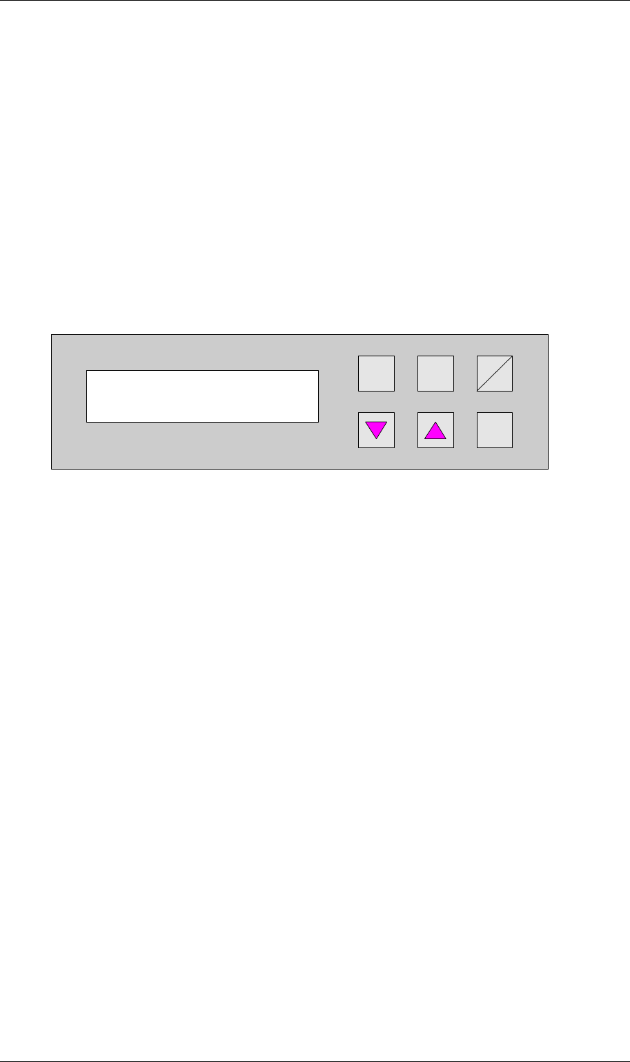
Hand
Stop
Start
Enter
Alt
Figure 53: Machine type
Machine type
Input module
Order No. 00192 169-01 User Manual - Productivity Lift
E_SPLFS03_V40_11_0300_200300_V1_14.doc Last update: 20.03.2000 - Version V 1.14 Page 44
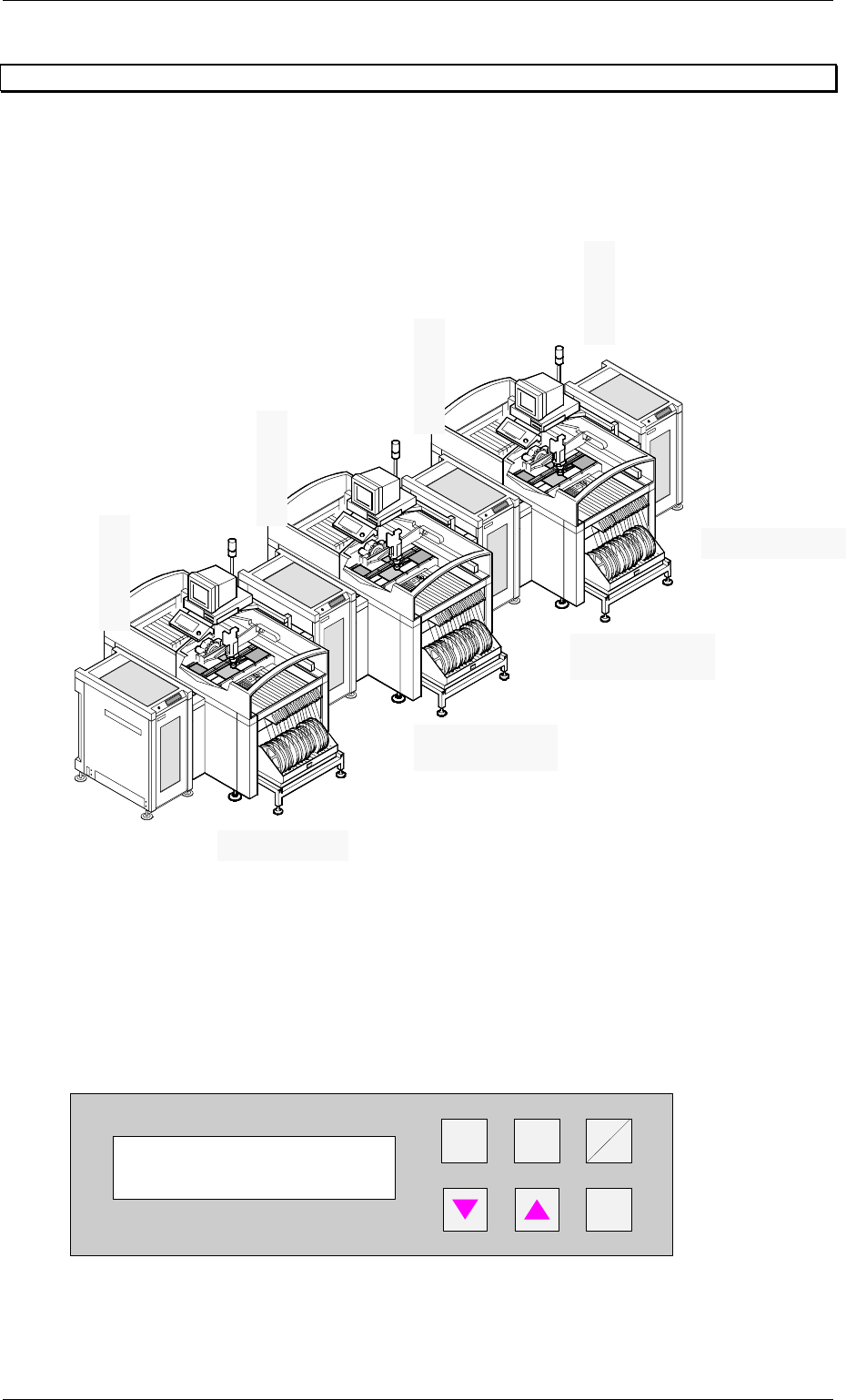
7.3 Ramp up mode / Ramp down mode
7.3.1 Example of Cluster with three Siplace units
7.3.2 Ramp up mode
PCB distribution parameter, which defines the loading sequence of the PCBs within a cluster
of Siplace units. The value of x depends on the number of Siplace units within a cluster (see
example 7.3.1).
The menu allows to set the value x between 0...9 .
+
Enter
Alt
Stop
Start
Figure 54: Ramp up mode
Ramp up mode
1 to x
Input module
Ramp up mode 1:1
Ramp down mode 1:0
Ramp down mode 1:2
Ramp up mode 1:0
Ramp down mode 1:1
Cluster module
Output module
Cluster module
Ramp up mode 1:2