SIPLACE HS50 电路图.pdf - 第114页
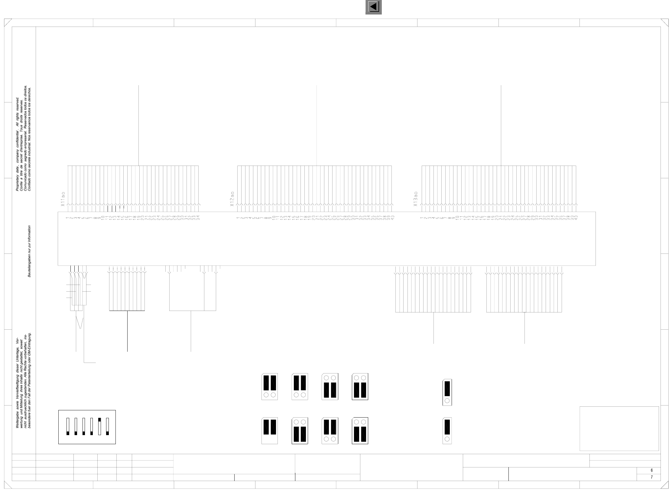
3 OPTIONS Circuit Diagrams 114 I 001 19025-0201 01LD3 Dual conveyo r , stationary sid e on th e right, wiring fo r contr ol 2, T SP200 (Sh. 7 o f 7) = SIEMENS AG + 8 12 3456 78 A B C D E F F X3ap 3 2 1 4 Lifti ng tabl e …
3 OPTIONS Circuit Diagrams 113
I
00119025-020101LD3 Dual conveyor, stationary side on the right,
wiring for control 1, TSP200 (Sh. 6 of 7)
Conveyor 1 plug X31am
Motor line, PCB conveyor
HS50 Conveyor 1
00351931
To conversion board
Conveyor 1 plug X32am
Sensor line 1, PCB conveyor
HS50 conveyor 1
00351932
Conveyor 1 plug X33am
To conversion board
Sensor line 2, PCB conveyor
HS50 conveyor 1
00351933
Stand.Status DateModified Name Orig. Repl. f. Replaced by
Check.
Date
Author
Sheet
Sh.
SMEMA
SiemensSiemens
J2
SMEMA
1
J2
1
Siemens
J1
1
J1
1
Siemens
1
SMEMA
J2
1
Error loop (Applies to 00349302 only)
J4
1
SMEMA
1
J1
Jumper settings
Error loop
J3
Input conveyor
J2
1
Output conveyor
1
J1
21
ON
6543
S1 address coding switch
TSP200
Motor + BB1
Motor - EB
Motor + EB
Motor - AB
Motor + AB
Motor + ZB
Motor - ZB
Motor - BB2
Motor + BB2
Motor - BB1
Motor B + BV
Motor B + BV
Motor A + BV
Motor A + BV
Motor A - BV
Motor A - BV
Motor B - BV
Motor B - BV
Bero BV
SB EB
GND
GND
+ 24 V
+ 24 V
SB ZB
SB AB
SB BB1
SB BB2
LS BB1 (res.)
LS BB2 (res.)
LS EB (res.)
LS ZB (res.)
LS AB (res.)
E4 (Opt.)
Bero HT 2 u
+ 24 V
GND
ESCH BRZ
Bero HT 1 o
Bero HT 1 u
Bero HT 2 o
ESCH BRA
E3 (Opt.)
Ventil ST BB1
Ventil ST BB2
Code 1 (Opt.)
Code 2 (Opt.)
Code 3 (Opt.)
Bero ST BB1
Bero ST BB2
SB UELP
E1 (Opt.)
E2 (Opt.)
Code 1 (Opt.)
Code 2 (Opt.)
Code 3 (Opt.)
E4 (Opt.)
E5 (Opt.)
E6 (Opt.)
A1 (Opt.)
A2 (Opt.)
A3 (Opt.)
E1 (Opt.)
E2 (Opt.)
E3 (Opt.)
VCC
E5 (Opt.)
E6 (Opt.)
A1 (Opt.)
A2 (Opt.)
A3 (Opt.)
GND
00348267 00348267 00348267
HT2o
SMD-Placement System Siplace HS50
Product status
Doc. status
Function status
To conversion board
Lifting table 2, top
Lifting table 2, bottom
ST
UELP
SB
HT2u
LS Light barrier
Excess length PCB
Stopper
Sonar prox. switch
Lifting table 1, bottom
Abbreviations
ESCH
BB2
EB
BRZ
BV
BRA
AB
BB1
HT1o
HT1u
E
A
Width narrower
Limit switch
Input conveyor
Width adjustment
Lifting table 1, top
Input
Placement sector 2
Width wider
Placement sector 1
Output conveyor
Output
(TSP200 or TSP200_M)
00349302 or 00353442
wh gnbn
ye ye
gn
bn
wh
ye
wh
bn
gn
n.c.
Dual conveyor, stationary side on the right
Wiring for control 1
10
9
234567
14
17
20
19
n.c.
n.c.
n.c.
6
5
4
7
10
9
n.c.
n.c.
n.c.
n.c.
n.c.
n.c.
n.c.
6
5
4
7
power supply
00352646
8
13
12
11
16
15
7
10
9
8
n.c.
n.c.
n.c.
n.c.
n.c.
n.c.
1 8
12345
X22ao
X21ao
Adapter cable:
3
2
1
6
5
4
18
X2ao
678
A
B
C
D
E
FF
E
D
C
B
3
2
X1ao
Interface preceding
machine
00303036
00303036
Interface succeeding
machine
V_GND_24VDC
V_+24VDC
V_SMEMA
V_Stoersign.
V_GND_24VDC
V_Erlaubnis
N_+24VDC
1
4
P5V
P24V
P40V
M digital
M
M
CANL
CANH
CAN-RES
n.c.
n.c.
n.c.
CAN bus
125kBits/s
00335323
Conveyor control, conveyor 1 ao
6
X6ao
3
2
1
4
Lifting table 2
5
6
M analog
Control:
Lifting table motors
00333592
Key
Key
X3ao
3
2
1
4
Lifting table 1
5
15.03.00
01
01
02
Ha
Ha
Ha
PL EA1 E
00119025-020101LD3
#
Haas
15.03.00
15.03.00
15.03.00
=
SIEMENS AG
+
FOR INFORMATION ONLY
This document will
not be replaced when
modifications are made!
16
15
14
17
20
19
18
N_SMEMA
N_GND_24VDC
N_Stoersign.
N_Abgegeben
n.c.
n.c.
V_Stoersign.
N_Stoersign.
n.c.
To plug X21ap
CAN-IR
n.c.
5 M analog
V_Angekommen
n.c.
n.c.
n.c.
n.c.
A
N_Anforderung
N_GND_24VDC
1
2
3
3
2
1
8
13
12
11
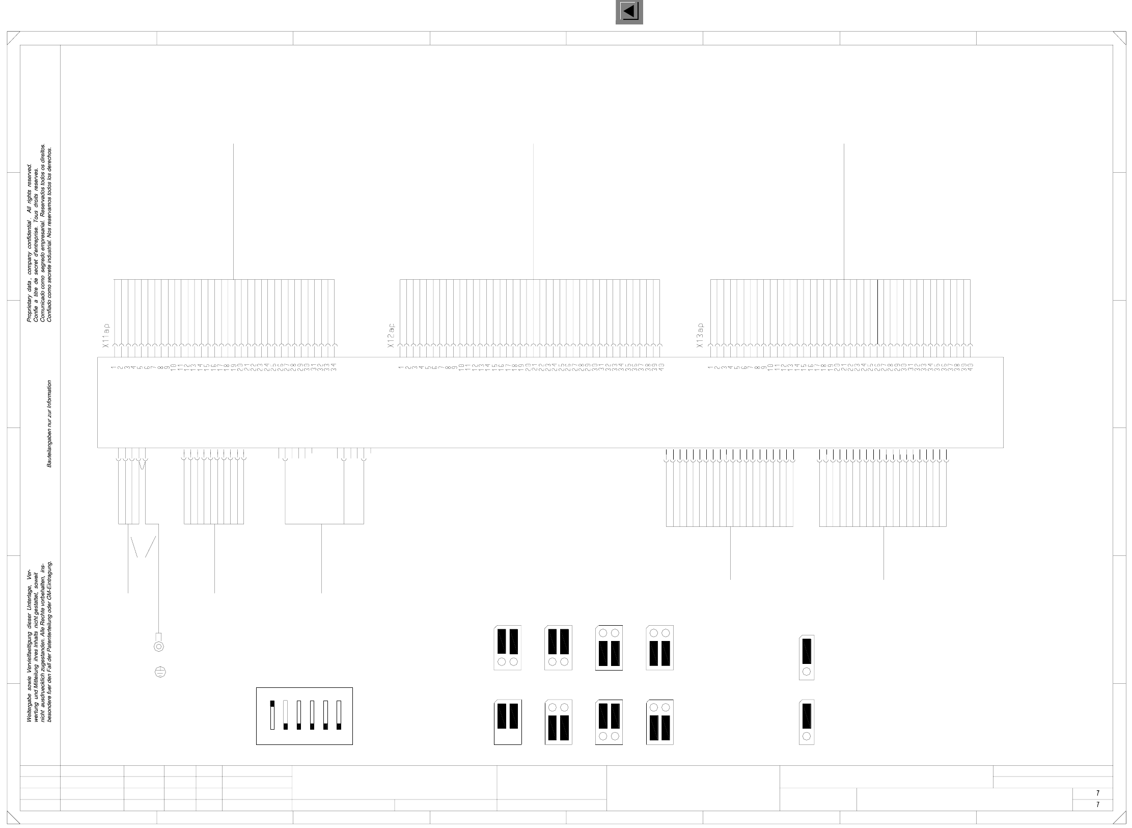
3 OPTIONS Circuit Diagrams 114
I
00119025-020101LD3 Dual conveyor, stationary side on the right,
wiring for control 2, TSP200 (Sh. 7 of 7)
=
SIEMENS AG
+
8
12345678
A
B
C
D
E
FF
X3ap
3
2
1
4
Lifting table 4
5
6
X6ap
n.c.
n.c.
n.c.
n.c.
n.c.
n.c.
n.c.
n.c.
n.c.
n.c.
n.c.
n.c.
n.c.
n.c.
n.c.
n.c.
3
2
1
4
Lifting table 3
5
6
M analog
Control:
lifting table motors
00333592
Key
Key
SMD-Placement System Siplace HS50
Product status
Doc. status
Function status
1x1.5mm² bk
Conveyor 2 plug X31an
To conversion board
Motor line, PCB conveyor
00353230
HS50 Conveyor 2
Conveyor 2 plug X32an
To conversion board
Sensor line 1 for PCB conveyor
HS50 Conveyor 2
00353231
Conveyor 2 plug X33an
To conversion board
HS50 Conveyor 2
Sensor line 2 for PCB conveyor
00353232
Stand.Status DateModified Name Orig. Repl. f. Replaced by
Check.
Date
Author
Sheet
Sh.
Lifting table 1, topHT1o
Lifting table 2, bottom
Lifting table 1, bottom
HT2o
ST
UELP
SB
HT2u
HT1u
LS
Lifting table 2, top
Excess length PCB
Stopper
Sonar prox. switch
Light barrier
Abbreviations
BB2
BRZ
BV
BRA
AB
BB1
ESCH
EB
E
A
Placement sector 2
Width narrower
Width adjustment
Width wider
Limit switch
Input conveyor
Input
Placement sector 1
Output conveyor
Output
Motor - BB1
Motor + BB2
Motor - BB2
Motor - ZB
Motor + ZB
Motor + AB
Motor - AB
Motor + EB
Motor - EB
Motor + BB1
Motor B - BV
Motor B - BV
Motor A - BV
Motor A - BV
Motor A + BV
Motor A + BV
Motor B + BV
Motor B + BV
LS AB (res.)
LS ZB (res.)
LS EB (res.)
LS BB2 (res.)
LS BB1 (res.)
SB BB2
SB BB1
SB AB
SB ZB
+ 24 V
+ 24 V
SB EB
Bero BV
GND
GND
E4 (Opt.)
Bero HT 2 u
ESCH BRA
Bero HT 2 o
Bero HT 1 u
Bero HT 1 o
ESCH BRZ
+ 24 V
GND
E3 (Opt.)
E2 (Opt.)
E1 (Opt.)
A3 (Opt.)
A2 (Opt.)
A1 (Opt.)
E6 (Opt.)
E5 (Opt.)
E4 (Opt.)
Code 3 (Opt.)
Code 2 (Opt.)
Code 1 (Opt.)
E2 (Opt.)
E1 (Opt.)
SB UELP
Bero ST BB2
Bero ST BB1
Code 3 (Opt.)
Code 2 (Opt.)
Code 1 (Opt.)
Ventil ST BB2
Ventil ST BB1
E3 (Opt.)
A3 (Opt.)
A2 (Opt.)
A1 (Opt.)
E6 (Opt.)
E5 (Opt.)
VCC
GND
(TSP200 or TSP200_M)
00349302 or 00353442
Jumper settings
1
14
17
20
19
18
X2ap
X1ap
Interface preceding
machine
00303036
00303036
Interface succeeding
machine
V_GND_24VDC
V_+24VDC
V_SMEMA
E
D
C
B
A
N_Abgegeben
N_Anforderung
6
5
4
7
10
9
8
13
12
11
16
15
14
17
20
19
n.c.
n.c.
n.c.
n.c.
n.c.
Dual conveyor, stationary side on the right
Wiring for control 2
10
9
234567
7
10
9
8
3
2
1
4
P5V
P24V
P40V
M digital
M
M
CANL
CANH
V_Stoersign.
V_GND_24VDC
V_Angekommen
V_Erlaubnis
N_+24VDC
N_SMEMA
N_GND_24VDC
N_Stoersign.
Additional ground
N_GND_24VDC
V_Stoersign.
N_Stoersign.
n.c.
n.c.
n.c.
18
3
2
1
6
5
4
7
power supply
00352646
8
13
12
11
16
15
CAN-RES
n.c.
n.c.
n.c.
CAN-IR
n.c.
5 M analog
Mounting plate
PCB conveyor HS50
3
2
1
CAN bus
125kBits/s
00335323
X22ap
X21ap
Adapter cable for
3
2
1
6
5
4
01
01
02
Ha
Ha
Ha
Conveyor control, conveyor 2 ap
PL EA1 E
00119025-020101LD3
#
Haas
15.03.00
15.03.00
15.03.00
15.03.00
21
ON
3456
S1 address coding switch
Siemens
SMEMA
Input conveyor
Siemens
J2
1
SMEMA
J2
1
J2
1
Output conveyor
1
J1
Siemens
J1
1
J1
1
Siemens
SMEMA
J2
1
SMEMA
1
J1
1
Error loop (Applies to 00349302 only)
J4
1
Error loop
J3
TSP200
wh
bn
gn
gn
wh
bn
ye
ye
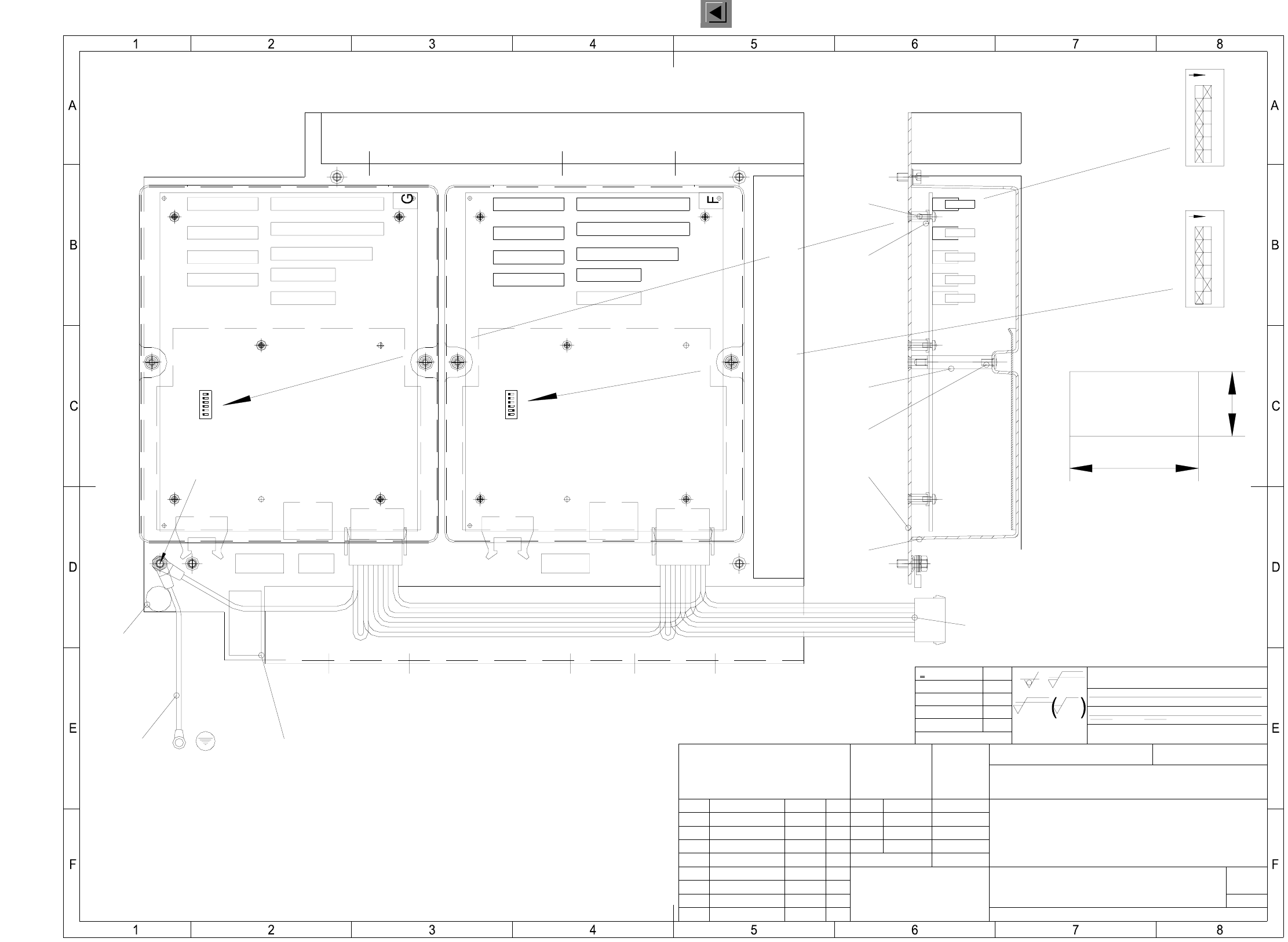
3 OPTIONS Circuit Diagrams 115
I
00349838-020101ZD3 Control, complete, HS-50 PCB dual conveyor, TSP200
XXX XXXXXXXXXXXXXXXXXXXX
XXXXXXXXXXXXXXXX
002
005
003
A
B
D
012
E
014
1
2
3
4
5
6
ON
013
1
2
3
4
5
6
ON
004
016
001
015
015
AA-BBBB-CCCC
00349838-02
SIEMENS PL EA 1
C
Status
FS 01
US 02
FS 02
Modified
new
AM9443
Name
Draeg
Frank
Draeg
Date
22.12.99
05.05.00
10.07.00
SIEMENS
PL EA
USMain no. FS ES SUA F
(Drawing number)
00349838-020101ZD3
Sheet
1
1Sh.
HS50 PCB dual conveyor, TSP200
Control, complete
(Material, semifinished products)
(Model or swage no.)
(Unmachined part no.)
Scale
1:2
Format
A3
Dimensional variations:
acc. to ISO 2768 mH
Degree of accuracy
medium
Author
Check.
Stand.
Date
22.12.99 Draeger
Name
Dimensional variations
R 100
z
z
R 2
R 6,3
z
Comprises
coordinates list:
einsatzgehaertet
gehaertet HRc
einsatzgehaertet
gehaertet HRc
Surface:
Tiefe:0,3/Tiefe:0,3/
Cable duct 65x46 l=335±5mm "X" means to break off one rib
Ground connection cable
Cable duct 65x30 l=300±5mm "X" means to break off one rib
Cable duct 65x30 l=250±5mm "X" means to break off one rib
Adapter cable 00352646-01
Conveyor 2Conveyor 1
Pos. of
binary switches
Label B
Pos. of
binary switches
Label A
Label C 00349838-FS
Label F: AO assembly designation
Label E: grounding
Label G: AP
Label D: inspection label
20
40
Weitergabe sowie Vervielfaeltigung dieser Unterlage, Verwer-
tung und Mitteilung ihres Inhalts nicht gestattet, soweit nicht
ausdruecklich zugestanden. Zuwiderhandlungen verpflichten zu
Schadenersatz. Alle Rechte fuer den Fall der Patenterteilung
oder GM-Eintragung vorbehalten.
Copying of this document, and giving it to others and the use
or communication of the contents thereof, are forbidden with-
out express authority. Offenders are liable to the payment of
damages. All rights are reserved in the event of the grant of
a patent or the registration of a utility model or design.
<6
>6...30
>30...120
>120...400
>400...1000
±0,1
±0,2
±0,3
±0,5
±0,8
010
011
006...009
00342987-01