SIPLACE HS50 电路图.pdf - 第151页
4 Printed Circui t Boards 151 I 0033589 2-010 101ND 4 855 board, S50 anti -cras h boar d 01 13 .03. 98 K L ATD TD M CH 2 SIEMENS AG 13.0 3.98 Klose Mounti ng diagr am, comp onent si de 4-lay er P C board 855 boar d S50 a…
4 Printed Circuit Boards 150
I
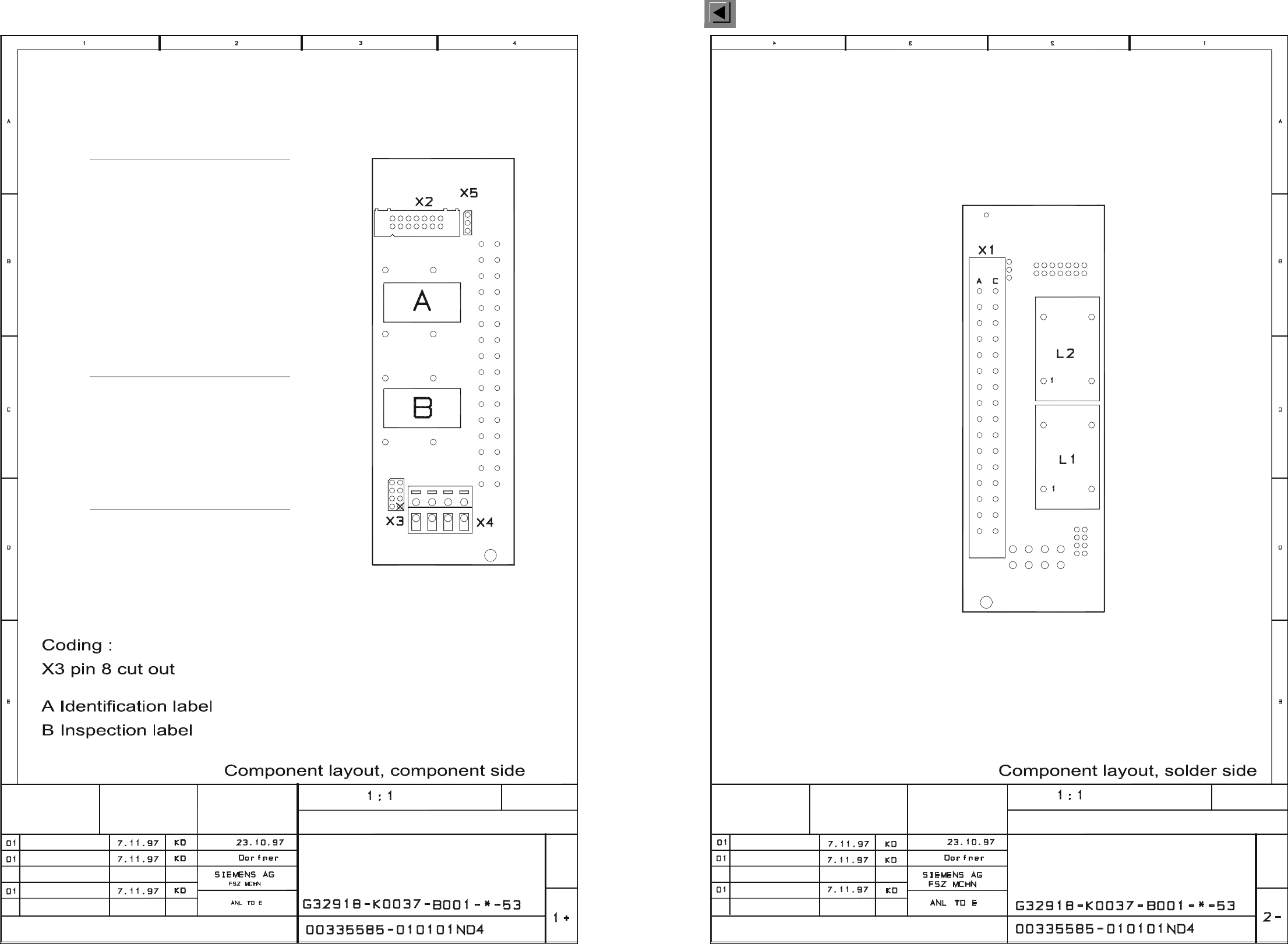
00335585-010101ND4 844 printed circuit board, backplane DC 2.5, component side (Sh. 1 of 2)
00335585-010101ND4 844 printed circuit board, backplane DC 2.5, solder side (Sh. 2 of 2)
BACKPLANE DC 2.5
LEITERPLATTE 844
Sheet
Stat. Modified Date Name
Date
Name
Function stat.
Product stat.
Document stat.
8
1, 8, 14
Link voltage
Tacho +
Tacho -
GND5, 6, 7, 8
- 15 V
+ 15 V
GND
Key
3
4
2
1
X4
Motor -
Motor +
Servo GND
Vnom
3
4
2
1
X3
10
9
Servo Ready
Servo Enable (+ 15 V)
Servo Enable
Sensor stop
N.u.
I²t
Ia - monitor
3
5
7
6
4
X2
2
Analog GND11
Tachometer12
Force13
PC BOARD
All documents viewed from component side
P
C
B
O
A
R
D
S
c
a
l
e
P
R
I
N
TED CIRCUIT BOARD 845
Sheet
D
a
t
e
N
a
m
e
Stat. Modified
D
a
t
e
N
a
m
e
Function stat.
Product stat.
Document sta
t
.
B
A
C
KPLANE DC 2.5
X
1
s
e
r
v
o
a
m
p
l
i
f
i
e
r
4 Printed Circuit Boards 151
I
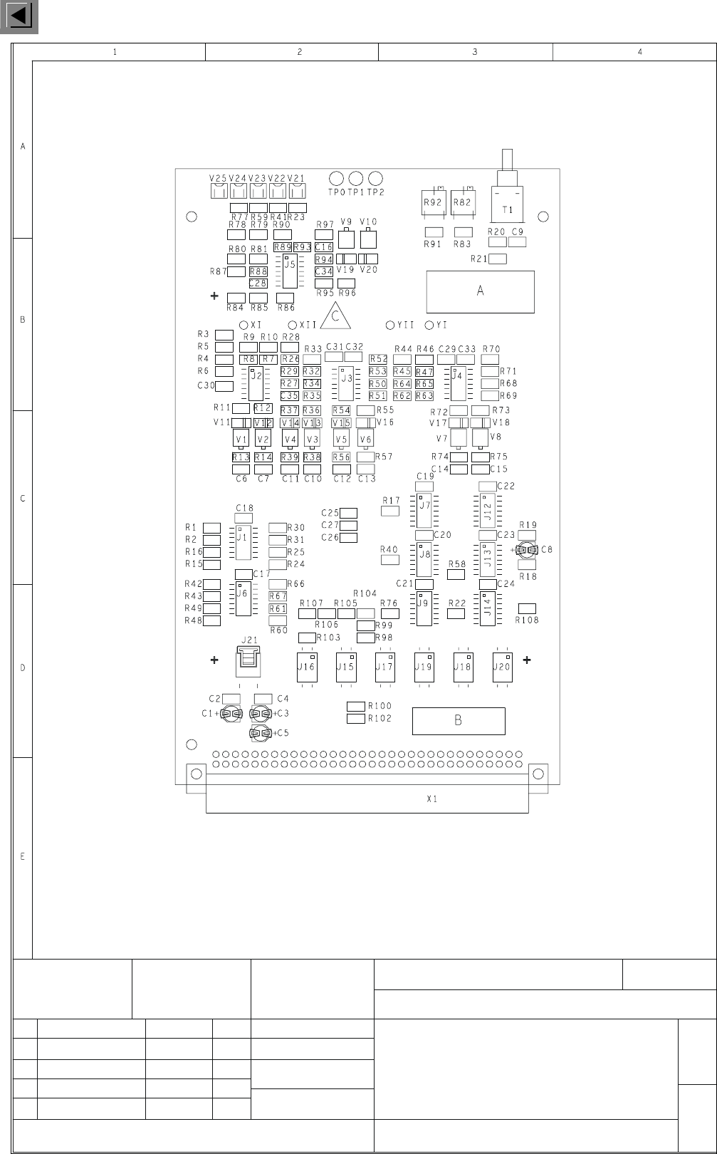
00335892-010101ND4 855 board, S50 anti-crash board
01 13.03.98 KL
ATD TD MCH 2
SIEMENS AG
13.03.98
Klose
Mounting diagram, component side
4-layer PC board
855 board
S50 anticrash board
G32918-K0084-B001-*-0017
00335892-010101ND4
1
1
A = ID label
B = inspection label
C = ESD label
Stat. Modified Date Name
Date
Name
Scale 1:1
Sheet
Sh.
4 Printed Circuit Boards 152
I
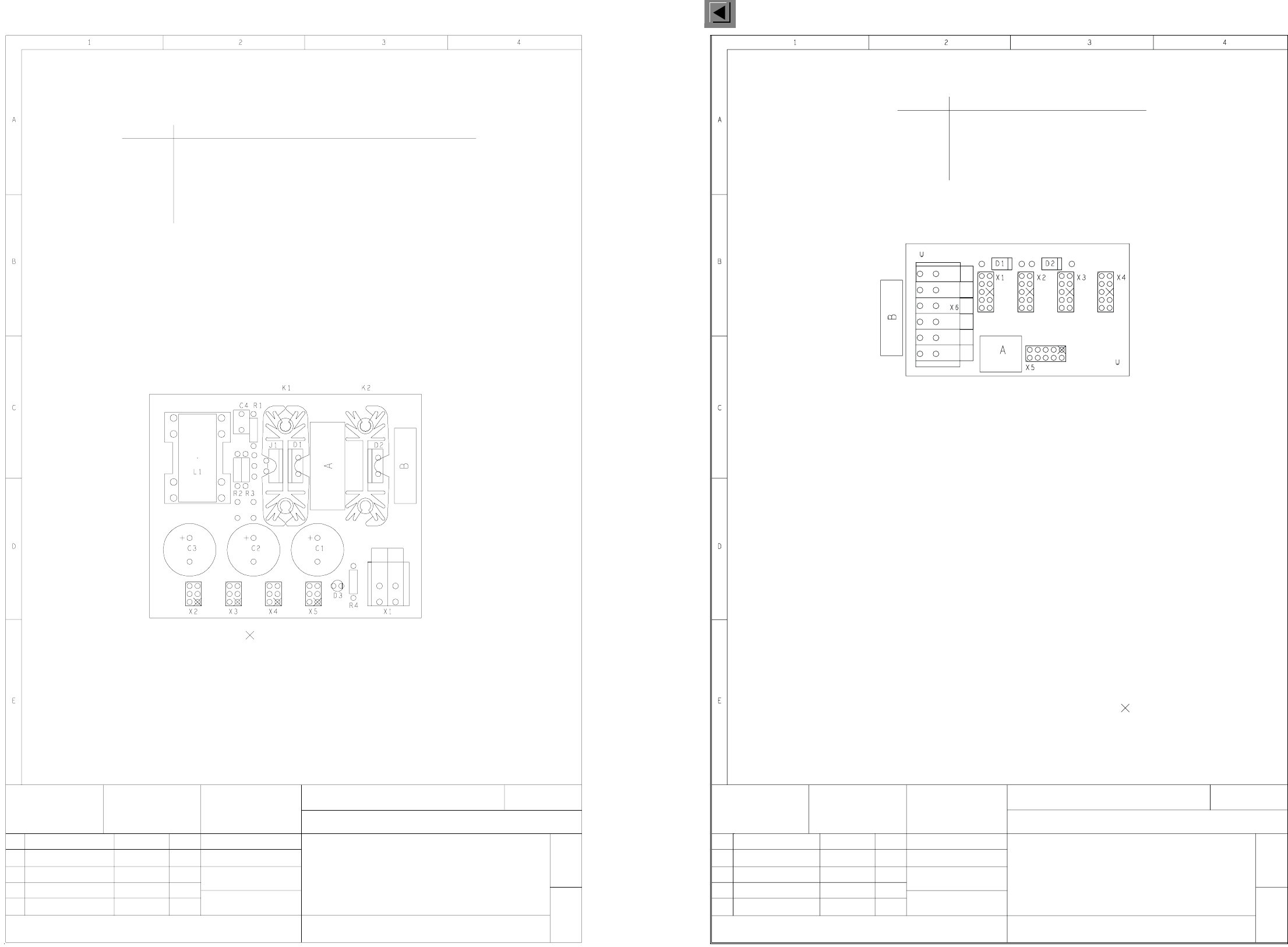
00336179-010101ND4 852 board, SM motors power supply
00336188-010101ND4 857 board, distributor illumination and HS-50 flash
01 28.01.98 KL
ATD TD MCH 2
SIEMENS AG
23.01.98
Klose
Mounting diagram, component side
2-layer PC board
852 board
Power supply
G32918-K0053-B001-*-0017
00336179-010101ND4
1
1
SM motors
= pinch off key pin
A = ID label
B = inspection label
Insert an insulating foil between J1, D1, D2 and the heat sink.
Stat. Modified Date Name
Date
Name
Scale 1:1
Sheet
Sh.
Assembly
1, 3
2, 4
X5
X4
X3
X1
X2
Connector
To X10ca gantry distributor 3, + 15 V, step motors, gantry 3
To X10da gantry distributor 4, + 15 V, step motors, gantry 4
To X10ba gantry distributor 2, + 15 V, step motors, gantry 2
+ 30 V
To X10aa gantry distributor 1, + 15 V, step motors, gantry 1
GND
4
31
2
A = Identificaton label
B = Inspection label, lateral to X6
Pinch off key pin
G32918-K0085-B001-*-0017
2-layer printed circuit board
Mounting diagram, component side
857 board
Distributor, illumination
and flash S50
00336188-010101ND4
1
1
ATD TD MCH 2
SIEMENS AG
09.03.98
Klose
09.03.98 KL01
Stat. Modified Date Name
Date
Name
Scale 1:1
Sheet
Sh.
To X7th control unit 00334808, flash line
To X9ca, gantry distributor 3, 00335413
Assembly
To X9da, gantry distributor 4, 00335413
To X9ba, gantry distributor 2, 00335413
To X9aa, gantry distributor 1, 00335413
X5
X4
X1
X2
X3
Connector
+ 5 V VZ illumination
4 + 24 V illumination 2
6
5 + 24 V illumination 3
GND
2
3
1
+ 24 V PCB illumination
+ 24 V illumination 1
Connector X6
71
28
39
410
511
612