SIPLACE HS50 电路图.pdf - 第69页
2 Circuit Diagr ams 69 I 0033449 0-010 201LD3 Pow er suppl y for l ifting table mo tors 1 - 4, con veyors 1 /2, TSP 100 (S h. 5 of 5) ELR1 12 10 gn 2 twin c onv eyor option with brak e 0033521 7 Sh. 2 MS6 2 4 6 4 2 rd 56…
2 Circuit Diagrams 68
I
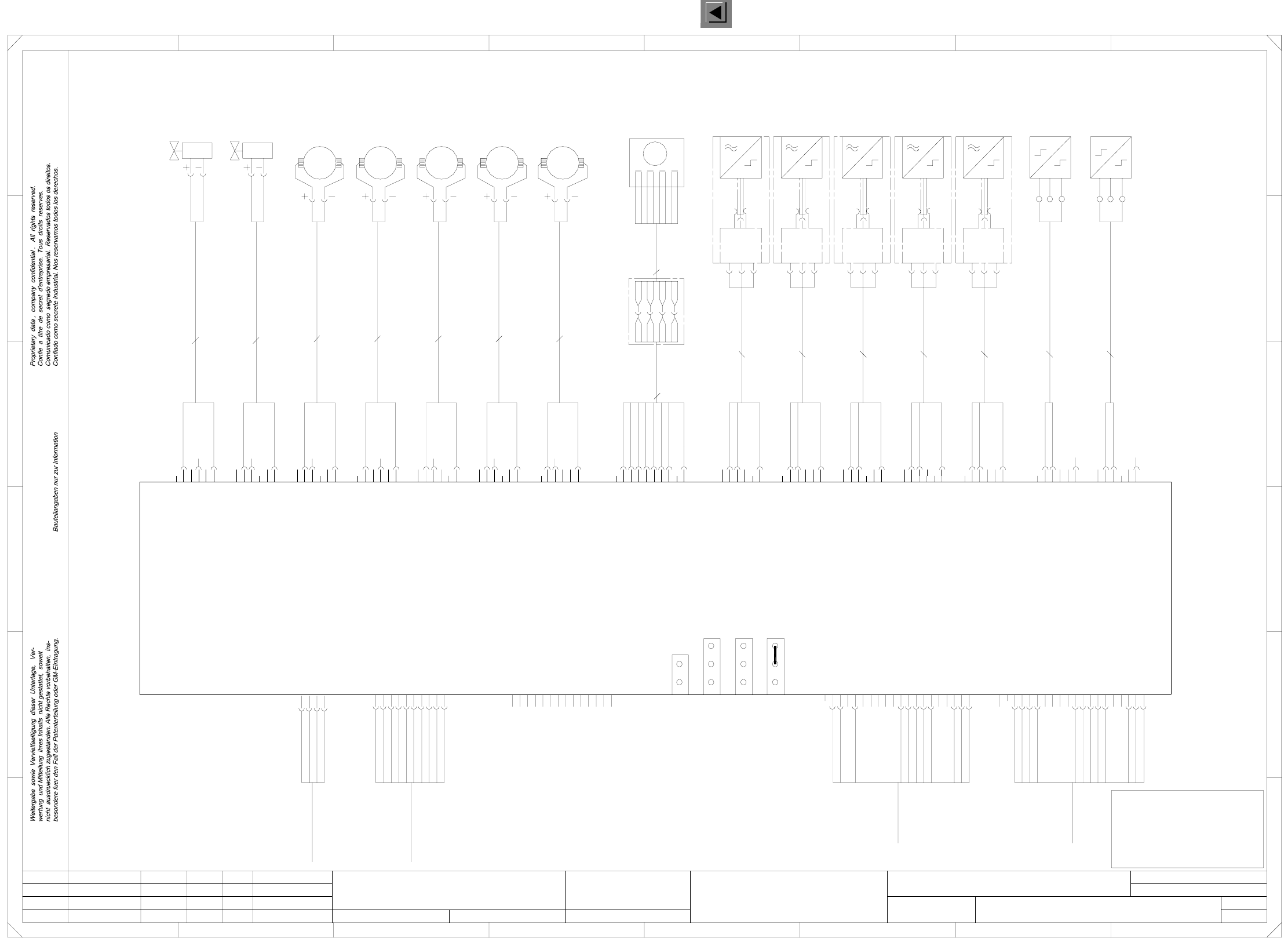
00334490-010201LD3 Conveyor module PCB2 (ap), conveyor 2, TSP100 (Sh. 4 of 5)
X12ap
wh
bn
X13ap
wh
bn
Key
Key
Key
bn
2
1
6
5
4
3
3
2
1
6
5
4
24V
2
1
6
I
0V
24V
I
1
6
5
4
3
2
M
versorgung
4
1
6
5
1
6
5
4
9
8
0V
24V
O
0V
24V
O
0V
4
3
2
24V
O
0V
24V
3
2
1
6
5
4
Key
Key
Key
Conveyor control PCB2 (ap)
3
2
3
2
1
6
5
4
S1_2 S2_2
placement
section 4
(conveyor 2)
buffer conveyor
(conveyor 2)
I
0V
24V
width
(conveyor 2)
Sonar
proximity switch
0V
3
2
1
6
5
1
6
5
1
6
5
0V
24V
I
0V
24V
O
CAN bus
125kBit/s
00335323
X34ap
3
2
24V
O
0V
4
7
10
9
O
0V
24V
O
0V
3
2
1
X15ap
X17ap
3
00336112
00336111
M2_2 M3_2 M5_2 B1_2
ceramic substrate
centering 3
(conveyor 2)
wh
Key
bn
X11ap
output conveyor
(conveyor 2)
adjustment
M4_2
placement
section 3
(conveyor 2)
input
(conveyor 2)
conveyor
Limit switch
(conveyor 2)
width adjustment
4
24V
I
4
3
2
5
4
7
10
9
8
bn
X8ap
00336106
wh
Key bn
X7ap
1
6
5
X3ap
bk
bl
bn
8
Key
bn
not used
X24ap
00336101
00336110
00336113
6
5
4
Key
bn
X25ap
00336102
Z5_2
Valve
B5_2
output
(conveyor 2)
conveyor
X14_2a
X15_2b
X15_2a
00336103
wh
M1_2
X17_2a
X18_2b
X18_2a
not used
Motor
input conveyor
(conveyor 2)
Motor
Motor
Motor
(conveyor 2)
X30ap
3
0V
24V
I
wh
bn
X9ap
00336105
wh
Key
Programming
interface
3
2
1
6
5
00336107
wh
Key
9
8
13
12 bk
bl
bn
bk
bl
bn
Z4_2
Valve
ceramic substrate
00336109
00336120
00336119
buffer conveyor
(conveyor 2)
B4_2
placement
(conveyor 2)
section 4
13
12
11
16
15
14
17
X16_2b
X16_2a
X17_2b
X35ap
X2ap
X1ap
narrower
not used
Sonar
proximity switch
Sonar
proximity switch
Sonar
Motor
Motor
Key
2
1
6
1
Strom-
11
14
13
12
00336117
A5_2
00336118
00337726
00337726
00337726
00337726
4
7
10
br/wh
or/wh
rd
ye
11
16
15
14
17
20
X14_2b
B2_2
placement
centering 4
(conveyor 2)
wh
5
4
7
10
9
8
(conveyor 2)
Cable: sonar prox. switch
(conveyor 2)
20
19
18
Cable: sonar prox. switch
(conveyor 2)
Limit switch
width adjustment
wider
IF preceding
machine
00342658
proximity switch
Sonar
proximity switch
bn
X10ap
00336104
00336114
A2_2
00336115
A3_2
00336116
A4_2
bn
wh
bn
P3/5
P3/6
P2/0
P2/1
00337726
bn
or
L+
S
L-
L+
rd/wh
ye/wh
To
plug X2ap
To
plug X1ap
19
18
3
(conveyor 2)
section 4
B3_2
Cable: sonar prox. switch
input conveyor
plcmt section 4
buffer conveyor
plcmt section 3
output conveyor
n.c.
n.c.
n.c.
n.c.
n.c.
n.c.
n.c.
Cable: sonar prox. switch
(conveyor 2)
n.c.
M6_2
not used
not used
Cable: sonar prox. switch
(conveyor 2)
Limit switch for width
adjustment wider (conveyor 2)
Limit switch for width
00342658
IF suceeding
machine
X33ap
3
2
4
2
1
4
wh
A
B
C
D
E
FF
L+
S
L-
Cable: valve for ceramic substrate
E
S
L-
L+
screen
screen
screen
00335234
Cable: valve for ceramic substrate
Cable: Motor
2
1
6
n.c.
n.c.
n.c.
n.c.
n.c.
n.c.
1234 8
12
n.c.
n.c.
n.c.
SMEMA standard 2-3
not used
not used
not used
not used
=
SIEMENS AG
+
PLEASE NOTE
This document will
not be replaced in case
of modifications !
wh
(conveyor 2)
input conveyor
placement section 4
bn
wh
2
1
6
5
4
Key
3
wh
centering 3
(conveyor 2)
5
4
3
2
0V
Key
Key
X14ap
bk
bl
bn
X16ap
4
3
2
4
24V
I
7
10
3
2
1
6
5
bl
bn
Key
1
6
5
4
bk
X18ap
adjustment narrower (conveyor 2)
2
1
_
Cable: Motor
M
345678
A1_2
M
_
00336108
(conveyor 2)
bn
wh
centering 4
S_Arrived
D
C
B
A
screen
screen
n.c.
S_Permission
S_Transferred
S_Request
5
4
n.c.
n.c.
n.c.
SMEMA standard 2-3
Reset
X31ap
X32ap
X27ap
Error loop
Siemens standard 1-2
3
4
Key
Key
Siemens standard 1-2
Cable: Motor
(conveyor 2)
bn
wh
567
3
1
4
(conveyor 2)
M
_
buffer conveyor
placement section 3
output conveyor
P_GND_24VDC
P_Arrived
P_Permission
P_Transferred
P_Request
P_GND
S_+24VDC
S_SMEMA
S_GND_24VDC
S_FaultSignal
+
-
+
-
S_GND_24VDC
P2/2
P2/3
P2/4
P5/5
P5V
P24V
P30V
M
M
_
Cable: Motor
L-
S
L+
L-
S
1
bl
rd
00343136
width
P_FaultSignal
S_FaultSignal
4
3
1
4
M
_
Cable: Motor
bn
3
1
P_GND_24VDC
P_+24VDC
P_SMEMA
P_FaultSignal
bn
or
br/wh
or/wh
rd
ye
rd/wh
ye/wh
A
+
A
-
B
8-pole
+
adjustment
Motor for width
(conveyor 1)
adjustment
P5/6
P5/7
P5/8
P5/9
P2/15
P5/4
_
M
wh
bn
(conveyor 2)
wh
bn
(conveyor 2)
or
or/wh
rd
rd/wh
ye
ye/wh
8-pole
00343137
X148
Cable: motor
(conveyor 1)
B
-
bn
br/wh
M
CANH
CANL
3
1
4
11.02.98
01
02
01
Leh
Leh
Leh
wh
bn
gn
ye
gy
pk
PL EA1 E
00334490-010201LD3
Conveyor module PCB2 (ap)
#
Haas
11.02.98
11.02.98
11.02.98
Function status
Product status
Doc. status
SMD Placement System SIPLACE HS50
(conveyor 2)
Status Modified NameDate Stand. Orig. Replacement for Replaced by
Author
Date
Check.
Sheet
Sh.
2 x 0,25mm²
2 x 0,25mm²
2 x 0,34mm²
2 x 0,34mm²
2 x 0,34mm²
2 x 0,34mm²
2 x 0,34mm²
3X0,34mm²
3X0,34mm²
3X0,34mm²
3X0,34mm²
3X0,34mm²
3X0,25mm²
3X0,25mm²
00329219
TSP100
Conveyor 1, jumper inserted
Conveyor 2, open
Interface, coding
Preceding machine
Interface, coding
Succeeding machine
2 Circuit Diagrams 69
I
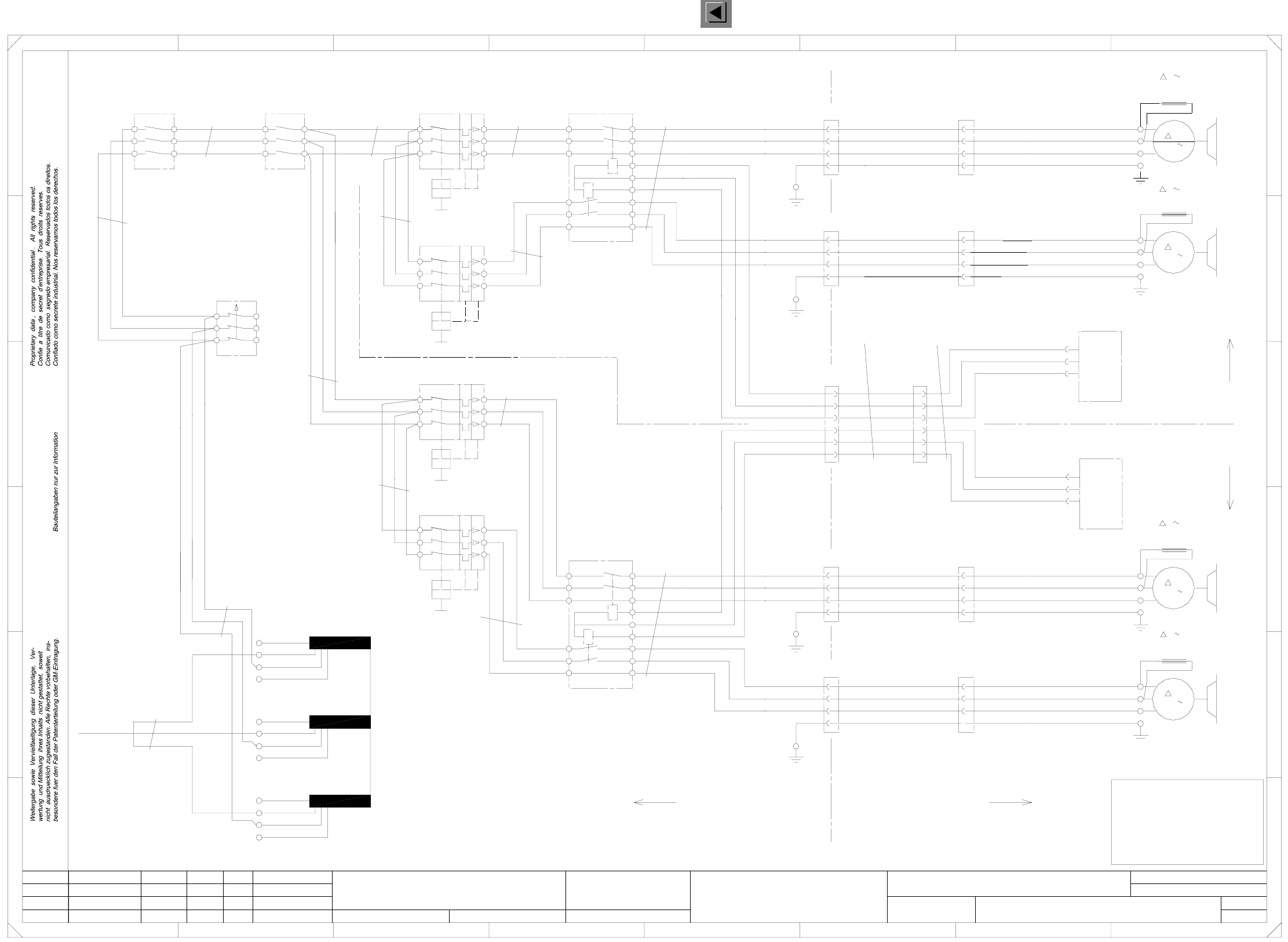
00334490-010201LD3 Power supply for lifting table motors 1 - 4, conveyors 1/2, TSP100 (Sh. 5 of 5)
ELR1
12
10
gn
2
twin conveyor option
with brake
00335217 Sh. 2
MS6
2
4
6
4
2
rd
56
SL
M
3
5
1
3
13
Control signals
lifting table motors
00333592
400V
230V
00337796
lifting table motors
bk(3)
ye/gn
00336121
placement section 4
Cable: lifting table motor
003352 16 Sh. 1
(conveyor 2)
204V
4mm²
T1
F3
4A
2
2
4
6
bk(3)
ye/gn
Motor lifting table 3
Motor lifting table 4
6
1
3
5
3
5
Null
X6am
4
8
6
3
4
2
3
4
2
3
X70
1
2
3
4
1
2
78
1
2
5
2
7
400V
230V
204V
440V
3X11_3
00333594
placement section 2
Cable: lifting table motor
X5
U
Control signals
extension
2
5
X3am
SLIO module
PCB1 (am)
(conveyor 1)
Motor: lifting table 1
M7_1
220V3
Lifting table motor 1
bk(1)
4
6
1
15
14
4
2
4
6
1
00335214 Sh. 2
Ctrl_lift 1
9
7
13
5
X11_4
4
2
5
3
1
11
9
Twin conveyor
option
ELR2
SLIO module PCB2
X6
U
V
3
4
bk(1)
K8
MS3
2
440V
1
2
X11_1
X11_2
bk(3)
ye/gn
220V3
Lifting table motor 4
003352 15 Sh. 1
(conveyor 1)
V
W
EEP
204V
440V
400V
230V
bk(3)
ye/gn
with brake
00335215 Sh. 2
X3an
SLIO module
PCB2 (an)
bk(2)
bk(3)
ye/gn
3
5
SZ2 SZ3
infeed
4mm²
1
11
X8_2
X73
1
14
15
X11_5
6X11_6
X5_1
X5_3
X5_4
X5_2
W
EEP
X7_1
X7_3
X7_4
X7_2
X72
W
EEP
X6_1
bk(2)
bk(3)
ye/gn
X11
11
bk(1)
bk(2)
X8_3
X8_4
3
4
2
U
V
Motor: lifting table 2
M8_1
220V
00333594
placement section 1
Cable: lifting table motor
003352 14 Sh. 1
M
3
00335216 Sh. 2
Transformer
MS5
2
4
X6an
X6an
ELR2
with brake
4
2
5
3 rd
rd
1
bk(1)
2
X6am
Twin conveyor
option
Ctrl_lift 2
Ctrl_lift 3
Ctrl_lift 4
Null
11
bk(1)
X6_3
X6_4
X6_2
X71
V
W
EEP
X8_1
rd
rd
wh
bn
gn
3
4
W
bk(1)
bk(2)
3
Lifting table motor 2
bk(1)
bk(2)
678
A
B
C
D
6
1
3
12
10
8
6
W
SL
M
3
C
B
A
5
bk(2)
bk(3)
ye/gn
X7
U
V
X128
1
2
3
A
0V
A
5
X8
U
6
1
3
5
4
5
6
(W1)
(W2)
2
4
2
3
4
00336122
placement section 3
Cable: lifting table motor
003352 17 Sh. 1
ye
gy
pk
34
23
E
FF
rd
rd
U
V
45
E
D
12.03.98
01
02
01
Leh
Leh
Leh
5
12
U
V
W
SL
PL EA1 E
00334490-010201LD3
Power supply, lifting table motors 1-4
#
Haas
12.03.98
12.03.98
12.03.98
Function status
Product status
Doc. status
SMD Placement System SIPLACE HS50
(conveyor 1/2)
Status Modified NameDate Stand. Orig. Replacement for Replaced by
Author
Date
Check.
Sheet
Sh.
2.5mm²
2.5mm²
2.5mm² 1.5mm² 0.75mm²
2.5mm²
1.5mm²
1.5mm²
2.5mm²
2.5mm²
0.75mm²
1.5mm²
TSP100
=
SIEMENS AG
+
PLEASE NOTE
This document will not
be replaced in case
of modifications!
wh
bn
gn
wh
bn
Conveyor track 2
with
1
3
5
U
V
W
(conveyor 2)
SL
K2
K3
K4
K6
K7
ye/gn
bk(2)
M8_2
220V3
Lifting table motor 3
bk(1)
bk(2)
bk(3)
with brake
M7_2
MS4
0V
A
S50 power supply unit PCB transport, lifting table motors
(conveyor 1)
(conveyor 2)
Single conveyor
M
3
A
rd
2 Circuit Diagrams 70
I
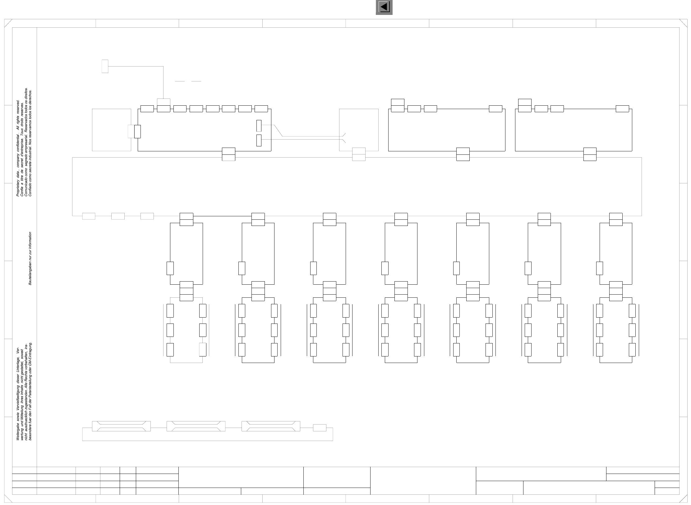
00334808-010102LD3 HS-50 control unit (Sh. 1 of 2)
A5
X27
X1tm
X7tm
X3tmX5tm
X2tmX4tmX6tm
X30
X1tp
X7tp
X1sn
X2sn
Axes tracks
Nominal values
Axis rear panel
X8sy
X3sg
X1sgX1sf
(sg)
X2sg
A7
X29
X1to
X7to
X3toX5to
X2toX4toX6to
Axes tracks
Nominal values
Axis rear panel
X7sy
X3sf
X5tr
X2trX4trX6tr
1
8
A
X1sk
A8 (sk)
X2sk
A9
X31
X1tq
X7tq
X3tqX5tq
X2tqX4tqX6tq
Axes tracks
Nominal values
Axis rear panel
X9sy
X3sh
X1sh
X2sh
(sh)
X8so
Communications assembly 2
(so)
A12
X34
X12sy
2456
X6snX7snX8sn
Communications assembly 1
(sn)
A11
X33
SMP bus ( 14-pin )
(sy)
A39
X11sy
X3sm
X1sm
X3tr
(sm)
X2sm
A10
X32
X1tr
X7tr
12
3
M54 machine controller
(sa)
A1
AMS bus
(7-pin)
X7sz
X14sy
Spare
X4sy
Spare
X3sy
Spare
F
45
E
D
C
B
A
E
3
B
F
C
D
76
A34 (to)
A35 (tp) A36
78
(tr)
X1ub
A44
Fan unit
(ub)
X1sy
X12saX11saX10saX9saX8saX7saX6sa
X4sa
X1sa
X5sa
X2sa X3sa
X2sy
X1sb
Data lines
Winchester /
Floppy M54
(sb)
A2
X6soX7so
(sz)
A40
Axis rear panel
X5sy
X3sd
X1sd
Axis board 1
(sd)
X2sd
A4
X26
X7tk
X3tkX5tk
X2tkX4tkX6tk
A31
Axes tracks
Nominal values
Axis rear panel
X1tk
(tk) A32 (tm) A33 (tn)
2.
1.
1.
Tek
Tek
Tek
2
00334808-010102LD3
X6sa
X1sv
00335693
To
video multiplexer
(tq) A37
X13sy
X1so
X2so
PL EA1 E2
1
HS50 control unit
#
Goller
21.01.1998
29.05.98
21.01.98
21.01.98
SMD-Placement System Siplace HS50
Product status
Doc. status
Function status
Status DateModified Name Stand. Orig. Replacement for Replaced by
Author
Date
Check.
Sheet
Sh.
=
SIEMENS AG
+
(sf)
X2sf
A6
X28
X1tn
Keyboard
Monitor
Serial
interface
Printer
Mouse
LAN 1
LAN 2
X3tpX5tp
X2tpX4tpX6tp
Com 1
Serial
interface
Com 2
Axis rear panels A31 - A37 are supplied with the cable harness !
Axis board 3
Axis board 4
Axis board 5
Axis board 6
Axis board 2
Axis board 7
CAN bus
CAN bus
V24 - 1
HS3L
CAN bus
CAN bus
V24 - 1
HS3L
Nominal values
Axes tracks
Nominal values
Axis rear panel
X10sy
X3sk
X7tn
X3tnX5tn
X2tnX4tnX6tn
Axes tracks
Nominal values
Axis rear panel
X6sy
X3se
X1se
Axes tracks
(se)
X2se