SIPLACE HS50 电路图.pdf - 第85页
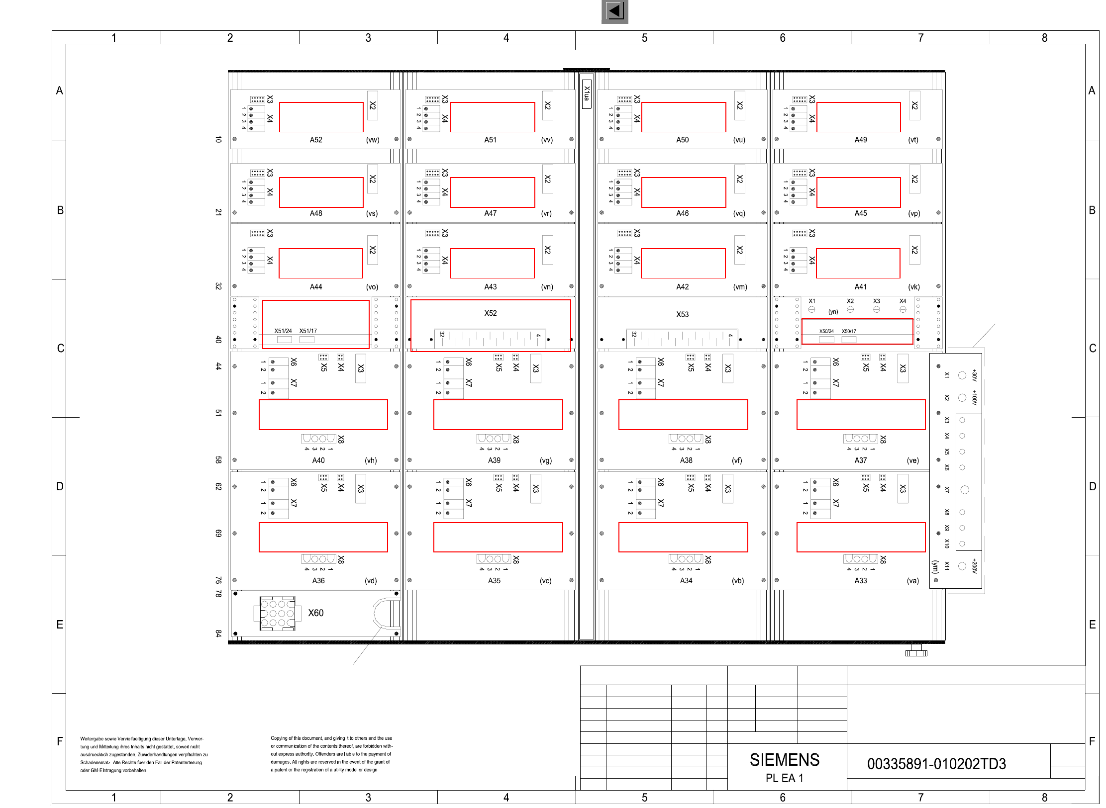
2 Circuit Diagr ams 85 I 0033589 1-010 202TD3 H S-50 se rvo unit without b oards , viewed f rom th e back (S h. 2 of 2) A3 HS50 servo unit, boards not instal led 2 (Viewed from the back) Potential distributor A44 (dp axi…
2 Circuit Diagrams 84
I
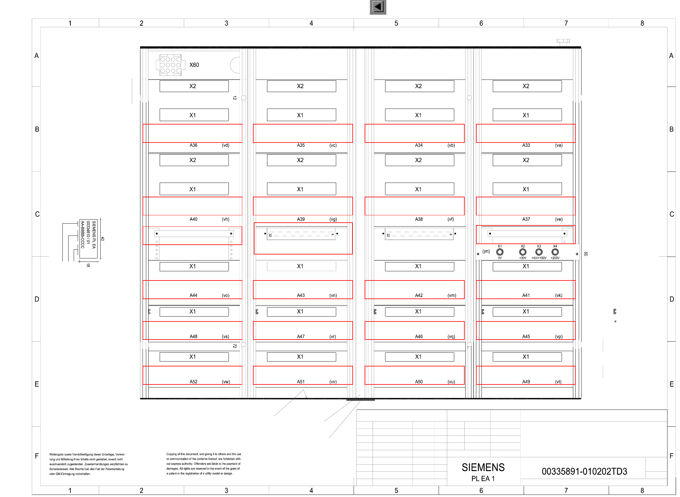
00335891-010202TD3 HS-50 servo unit without boards, viewed from the front (Sh. 1 of 2)
FS ES US UA S F
Function status
Product status
Doc. status
SMD Placement System SIPLACE HS50
Manufaturer/location of plant according to SN 37040
Date (year/month/day) according to SN 01007
Numeral
Identification: test eng., month, yearB: Inspection label
Font size 2.5 mm, material Scothcal 3698-E ( color AI RAL 9006)
Assembly inscription according to VA-F-510-001
Apply the following labels on the outer side (flush with the front panel):
A: ID label
* Note
26.01.99
Status Modified Date Name
Scale
Author
Check.
Stand.
Date
Name
(Drawing number)
Main no.
Sheet
Sh.
(Front view)
1
HS50 servo unit, boards not installed
A3
2
1:2
01.
01.12.1997 Hoffmann
01.12.97
07.12.98
26.01.99
Tek
Tek
Tek
02.
02.
( on bottom and front only)
with grounding clamps
Guide rails (4x)
by M3 movable nuts!
Anticrash board X50
Ballast circuit X53Netzteil X52
Anticrash board X51
(dp axis)
Backplane DC2,5
(Z axis)
Backplane DC2,5
(Star)
Backplane AC2,5
(Y axis)
Backplane AC12,5
(X axis)
Backplane AC12,5
(dp axis)
Backplane DC2,5
(Z axis)
Backplane DC2,5
(Star)
Backplane AC2,5
(Y axis)
Backplane AC12,5
(X axis)
Backplane AC12,5
(dp axis)
Backplane DC2,5
(Z axis)
Backplane DC2,5
(Star)
Backplane AC2,5
(Y axis)
Backplane AC12,5
(X axis)
Backplane AC12,5
(dp axis)
Backplane DC2,5
(Z axis)
Backplane DC2,5
(Star)
Backplane AC2,5
(Y axis)
Backplane AC12,5
(X axis)
Backplane AC12,5
The distance bushes for the cover plate
are fixedto the 12. or 72. latching point
by M3 movable nuts!
is fixed to the 50. latching point
A55 voltage meas. unit
Gantry IGantry IVGantry III Gantry II
* Note
Stay bar
Cover plate
See page 151
See page 149
See page 150
See page 150
See page 140
See page 140
2 Circuit Diagrams 85
I
00335891-010202TD3 HS-50 servo unit without boards, viewed from the back (Sh. 2 of 2)
A3
HS50 servo unit, boards not installed
2
(Viewed from the back)
Potential distributor A44
(dp axis)
Backplane DC2,5
(Z axis)
(Star)
(Y axis)
Backplane AC12,5
(X axis)
Backplane AC12,5
(Y axis)
Backplane AC12,5
(X axis)
Backplane AC2,5
(Star)
Backplane DC2,5
(Z axis)
(dp axis)
Backplane DC2,5
(dp axis)
Backplane DC2,5
Backplane DC2,5
(Z axis)
Backplane AC2,5
(Star)
Backplane AC12,5
(Y axis)
Backplane AC12,5
(X axis)
Backplane AC12,5
(Y axis)
Backplane AC12,5
(X axis)
Backplane AC2,5
(Star)
(Z axis)
Backplane DC2,5
(dp axis)
Backplane DC2,5
Gantry IIGantry III Gantry IV Gantry I
Edge protection
potential distributor
Cover
0-Volt
02.
02.
Tek
Tek
Tek
26.01.99
07.12.98
01.12.97
Hoffmann01.12.1997
01.
1:2
2
Anticrash board X51
Power supply unit Ballast circuit
Anticrash board X50
Fan unit assembly A44
Backplane AC12,5
Backplane AC2,5
Backplane DC2,5
Function status
Product status
Doc. status
SMD Placement System SIPLACE HS50
FSUAUSESFS
26.01.99
Status Modified Date Name
Stand.
Check.
Author
Scale
Date
Name
(Drawing number)
Main no.
Sheet
Sh.
See page 151
See page 140
See page 140
See page 149
See page 150
See page 150
2 Circuit Diagrams 86
I
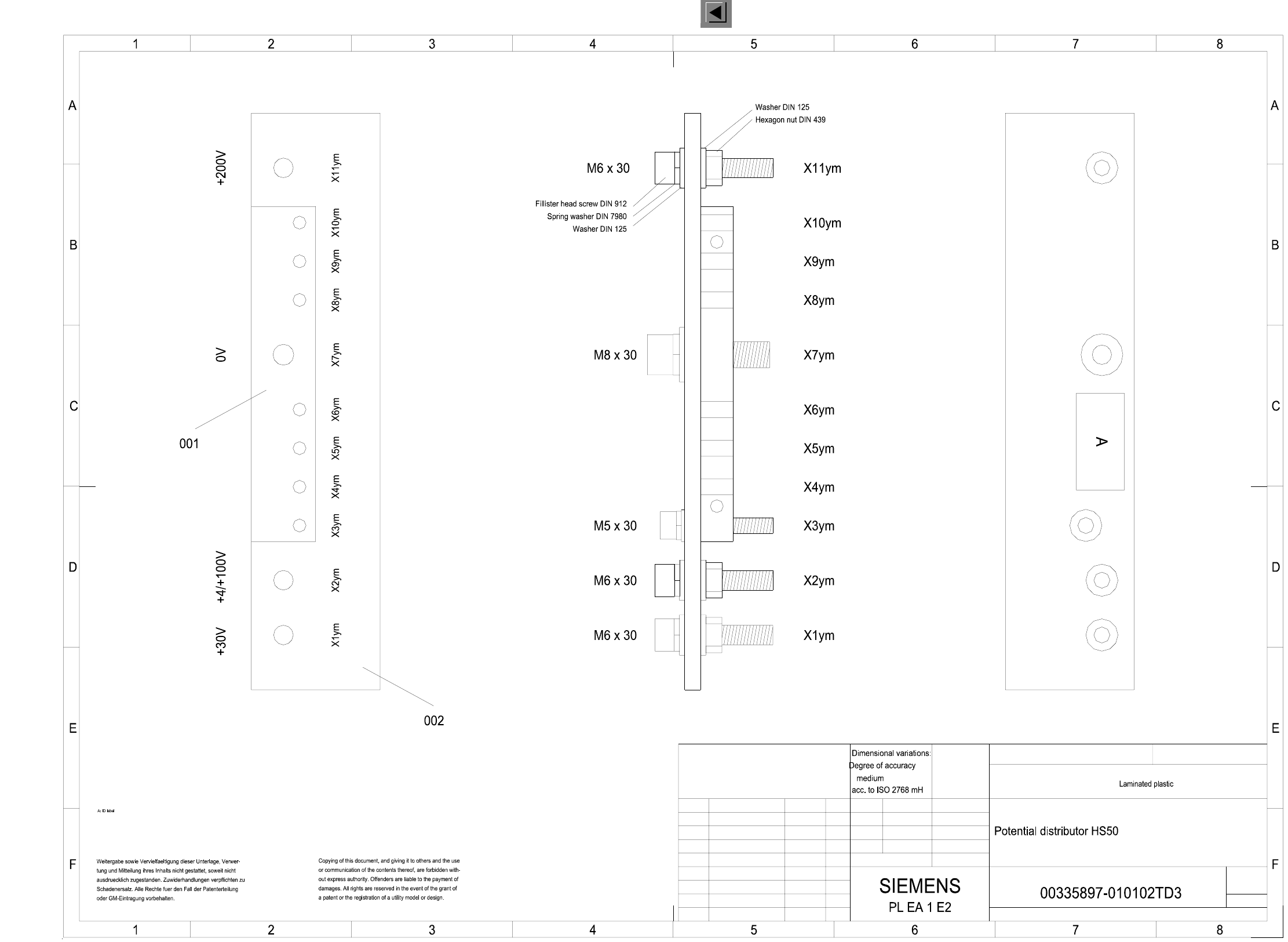
00335897-010102TD3 Potential distributor, HS-50
Status Modified Date Name
Date
Name
Stand.
Check.
Author
(Drawing number)
Main no.
Sheet
Sh.
(Model or swage no.)
(Material, semifinished products)
(Unmachined part no.)
1 : 1
1
A3
1
02.
01.
Tek
Tek
Tek
26.01.99
21.01.98
21.01.98
Hoffmann21.01.1998
01.
1
FSUAUSESFS
Scale
Format
Function status
Product status
Doc. status
SMD Placement System SIPLACE HS50
26.01.99