Autosite_Users_Manual.pdf - 第111页
Trans lation Fo rmats AutoSite User Manual B-13 POF (Programmer Ob ject File) Format, Cod e 14 The POF (Progr ammer Object Fil e) format provides a highly compact data format to ena ble translati on of high bit count lo …
Translation Formats
B-12 AutoSite User Manual
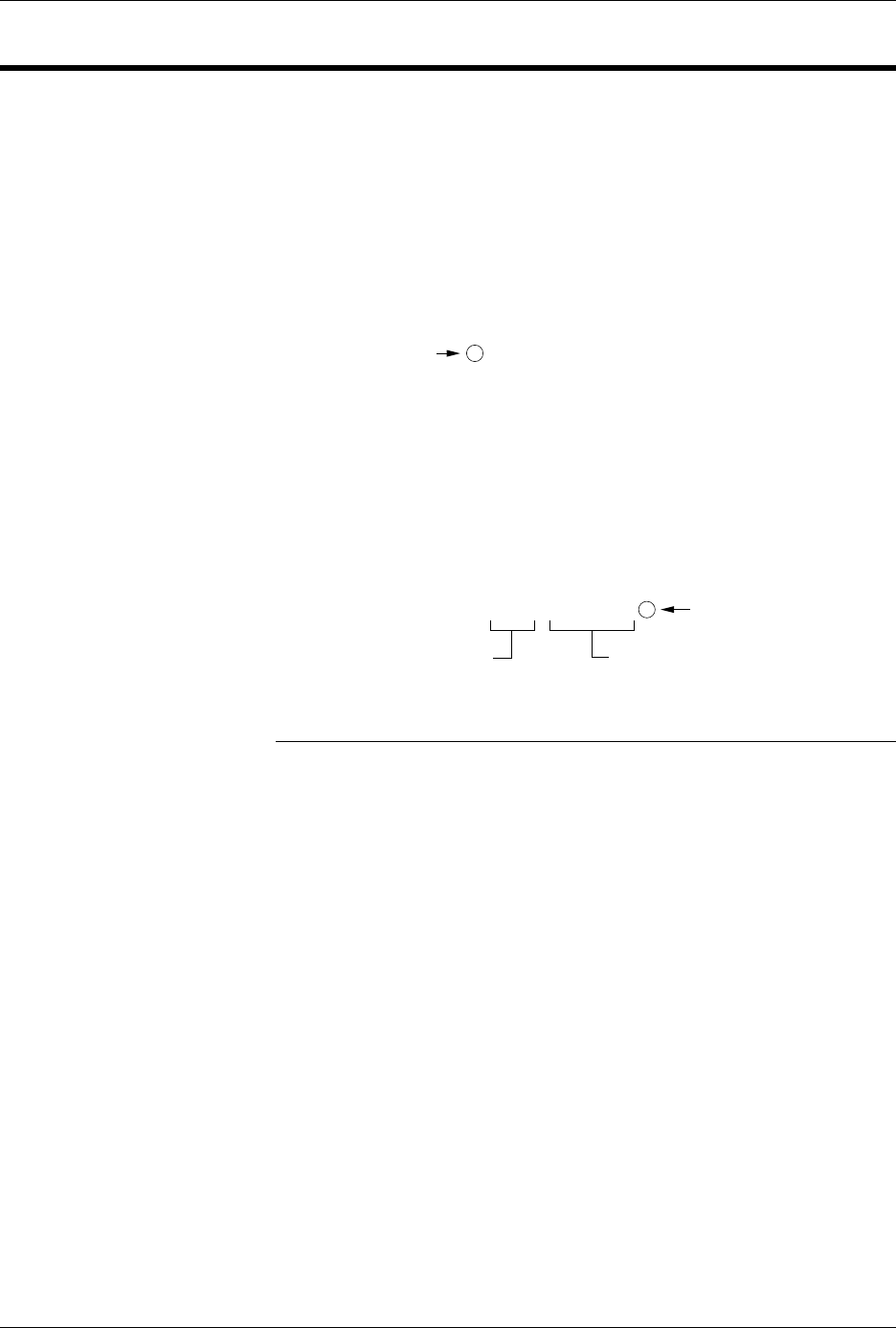
Spectrum Format, Codes 12 or 13
In this format, bytes are recorded in ASCII codes with binary digits
represented by 1s and 0s. During output, each byte is preceded by a
decimal address.
Figure B-5 shows sample data bytes coded in the Spectrum format. Bytes
are sandwiched between the space and carriage return characters and are
normally separated by line feeds. The start code is a nonprintable STX,
CTRL-B (or hex 02), and the end code is a nonprintable ETX, CTRL-C (or
hex 03).
Note: Data without a start or end code may be input to or output from the
programmer by use of the alternate data translation format code, 13
Figure B-5
An Example of Spectrum Format
0000 11111111
0001 11111111
0002 11111111
0003 11111111
0004 11111111
0005 11111111
0006 11111111
0007 11111111
0008 11111111
0009 11111111
0010 11111111
0011 11111111
0012 11111111
0013 11111111
0014 11111111
0015 11111111
End code is a
nonprintable EXT
4 or 8 data bits appear between the
space and the carriage return
Address Code is 4
decimal digits
Optional Start Code
is a nonprintable STX
0077-2

Translation Formats
AutoSite User Manual B-13
POF (Programmer Object File) Format, Code 14
The POF (Programmer Object File) format provides a highly compact
data format to enable translation of high bit count logic devices
efficiently. This format currently applies to MAX™ devices, such as the
Altera 5032.
The information contained in the file is grouped into “packets.” Each
packet contains a “tag,” identifying what sort of data the package
contains plus the data itself. This system of packeting information allows
for future definitions as required.
The POF is composed of a header and a list of packets. The packets have
variable lengths and structures, but the first six bytes of every packet
always adhere to the following structure.
struct PACKET_HEAD
{
short tag; /*tag number - type of packet */
long length; /*number of bytes in rest of packet */
}
A POF is read by the program examining each packet and if the tag value
is recognized, then the packet is used. If a tag value is not recognized, the
packet is ignored.
Any packet except the terminator packet may appear multiple times
within a POF. Packets do not need to occur in numerical tag sequence.
The POF reader software is responsible for the interpretation and action
taken as a result of any redundant data in the file, including the detection
of error conditions.
The POF format currently uses the following packet types.
Note: In the following packet type descriptions, one of the terms — Used,
Skipped, or Read — will appear after the tag and name.
Used: The information in this packet is used by the programmer.
Skipped: This information is not used by the programmer.
Read: This information is read by the programmer but has no direct
application.
Creator_ID
tag=1 Used
This packet contains a version ID string from the program which created
the POF.
Device_Name
tag=2 Used
This packet contains the ASCII name of the target device to be
programmed, for example, PM9129.

Translation Formats
B-14 AutoSite User Manual
Comment_Text
tag=3 Read
This packet contains a text string which may consist of comments related
to the POF. This text may be displayed to the operator when the file is
read. The string may include multiple lines of text, separated by
appropriate new line characters.
Tag_Reserved
tag=4 Skipped
Security_Bit
tag=5 Used
This packet declares whether security mode should be enabled on the
target device.
Logical_Address_
and_Data_16
tag=6 Read
This packet defines a group of logical addresses in the target device and
associates logical data with these addresses. The addresses comprise a
linear region in the logical address space, bounded on the low end by the
starting address and extending upward by the address count specified in
the packet.
Electrical_Address
_and_Data
tag=7 Used
This packet defines a group of electrical addresses in the target device
and associates data values with those addresses. The data field is
ordered in column-row order, beginning with the data for the least
column-row address, continuing with increasing row addresses until the
first column is filled, then incrementing the column address, etc.
Terminator
tag=8 Used
This packet signals the end of the packet list in the POF. This packet must
be the Nth packet, where N is the packet count declared in the POF
header. The CRC field is a 16-bit Cyclic Redundancy Check computed on
all bytes in the file up to, but not including, the CRC value itself. If this
CRC value is zero, the CRC check should be ignored.
Symbol table
tag=9 Skipped
Test Vectors
tag=10 Used
This packet allows the POF to contain test vectors for post programming
testing purposes. Each vector is a character string and uses the 20
character codes for vector bits defined in JEDEC standard 3A, section 7.0.
Electrical_Address_and_
Constant_data
tag=12 Skipped
Number of programmable
elements
tag=14 Read
This packet defines the number of programmable elements in the target
device.