Autosite_Users_Manual.pdf - 第71页
Operation AutoSite User Manual 3-13 Inserting the DIP or PLCC Base This section e xplains ho w to insert the DIP a nd PLCC Bases in to AutoSi te. About the Base Similar to a programming module, the DIP Base and PLCC Ba s…
Operation
3-12 AutoSite User Manual
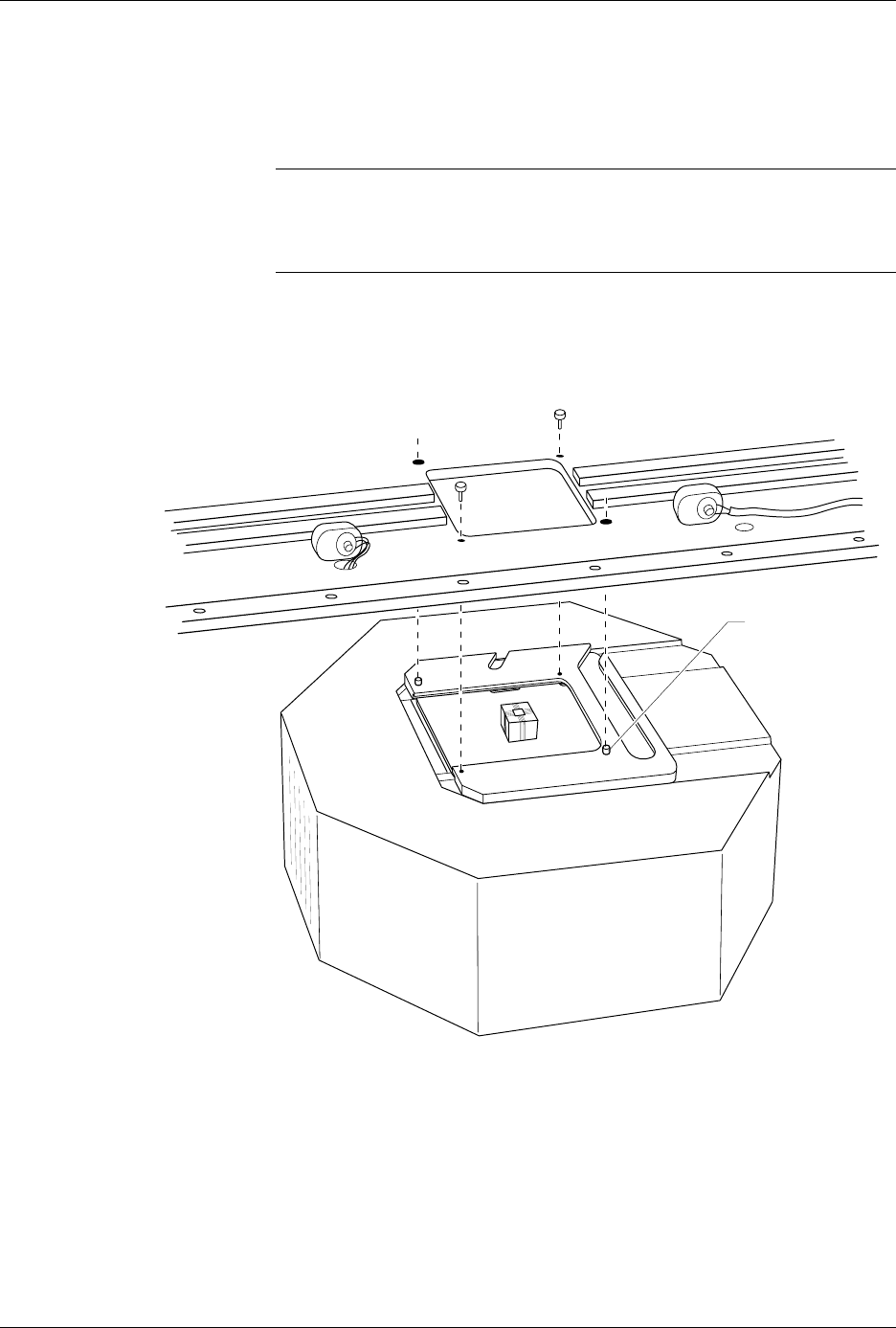
10. Position the pin driver head against the bottom of the handler. Using
the guide pins on the clamp ring, align the pin driver head with the
handler. Tighten the two thumbscrews to secure the pin driver head
to the handler.
Note: When properly connected to the handler, the clamp ring will be flush
against the handler.
7500 only: Replace the second pin driver head.
CAUTION: When the pin driver head is fully in position under the main
plate, make sure that no wires or air lines are pinched by the
head.
11. Readjust the height of the control unit (3000 and 7000 only).
You are finished changing the programming module.
Figure 3-8
Securing the Pin Driver Head to the Handler
1362-1
GUIDE PIN
(1 of 2)

Operation
AutoSite User Manual 3-13
Inserting the DIP or PLCC Base
This section explains how to insert the DIP and PLCC Bases into
AutoSite.
About the Base
Similar to a programming module, the DIP Base and PLCC Base serve as
the interface between a device and AutoSite. The DIP and PLCC Bases are
designed to help isolate programming problems and hardware problems.
For more information, see the section “Isolating Programming
Problems.”
Inserting a Base
Follow the procedure below to insert a Base into AutoSite.
Note: You can install and remove a Base with the power on as long as you are
not performing a device operation.
1. Make sure the handler is idle.
2. Clear all devices from the handler.
3. If the pin driver head is attached to a handler, remove the pin driver
head from the handler. See the handler manual for more information.
4. If a programming module is installed in the pin driver head, remove
the programming module from the pin driver head. Set the
programming module aside. See the handler manual for more
information.
CAUTION: Do not touch the pins that are exposed when you remove the
programming module.
5. Slide the compression handle onto the pin driver head. The
compression handle is shown in Figure 1-1.
Operation
3-14 AutoSite User Manual
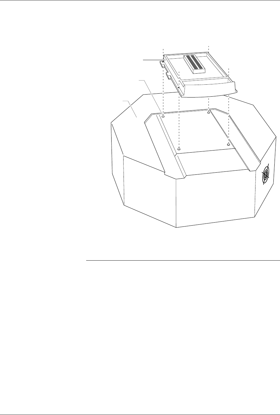
6. As shown in Figure 3-9, set the Base onto the pin driver head, making
sure the guide pins on the pin driver head line up with the guide
holes in the Base.
7. Squeeze the Base and the clamp ring together, securing the Base to
the pin driver head. You do not need to use excessive force.
CAUTION: You can damage AutoSite by squeezing too hard.
With the Base installed in the pin driver head, you can perform the
following procedures:
• Update AutoSite to a new version of system software. See the
User
Notes and Update Instructions
that accompany the new software.
• Program PLCC devices one at a time. See the section titled “Inserting
PLCC Devices and Using MatchBooks” for more information.
Figure 3-9
Aligning the Base on the Pin
Driver Head
1381-1
PIN DRIVER
HEAD
DIP BASE
GUIDE PIN
(1 OF 4)