Autosite_Users_Manual.pdf - 第32页
Setup and Ins tallation 2-10 Auto Site Us er Man ual 9. As show n in Figure 2-10, slide the cla mp ring onto the pin driver head, securing the prog ramming module in place. CAUTION: You may ha ve to push down on the prog…
Setup and Installation
AutoSite User Manual 2-9
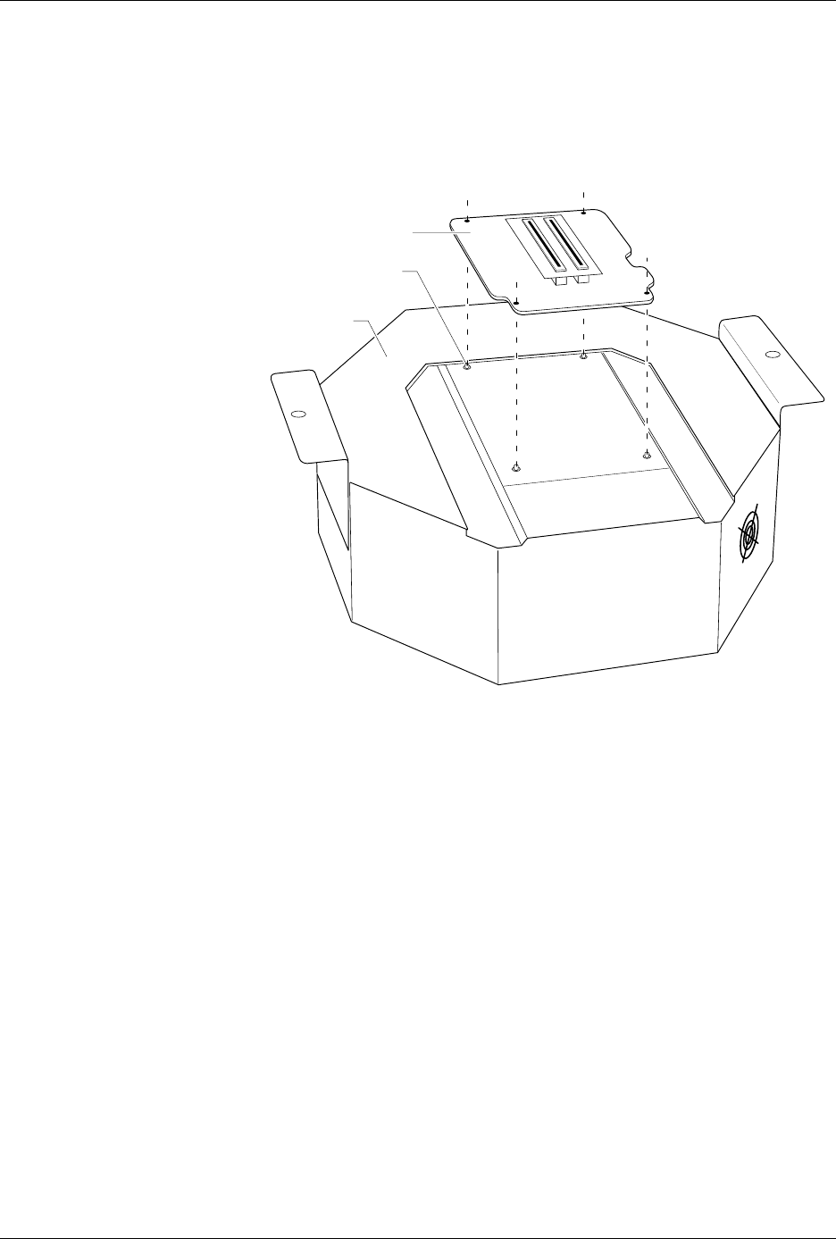
8. Select a programming module that matches the contactor set you
attached to the pin driver head mounting plate in steps 4 and 5. As
shown in Figure 2-9, set the programming module onto the pin driver
head, making sure the guide pins on the pin driver head line up with
the guide holes in the programming module.
Figure 2-9
Aligning the Programming Module
on the Pin Driver Head
1350-1
PROGRAMMING
MODULE
PIN DRIVER
HEAD
GUIDE PIN (1 of 4)
Setup and Installation
2-10 AutoSite User Manual
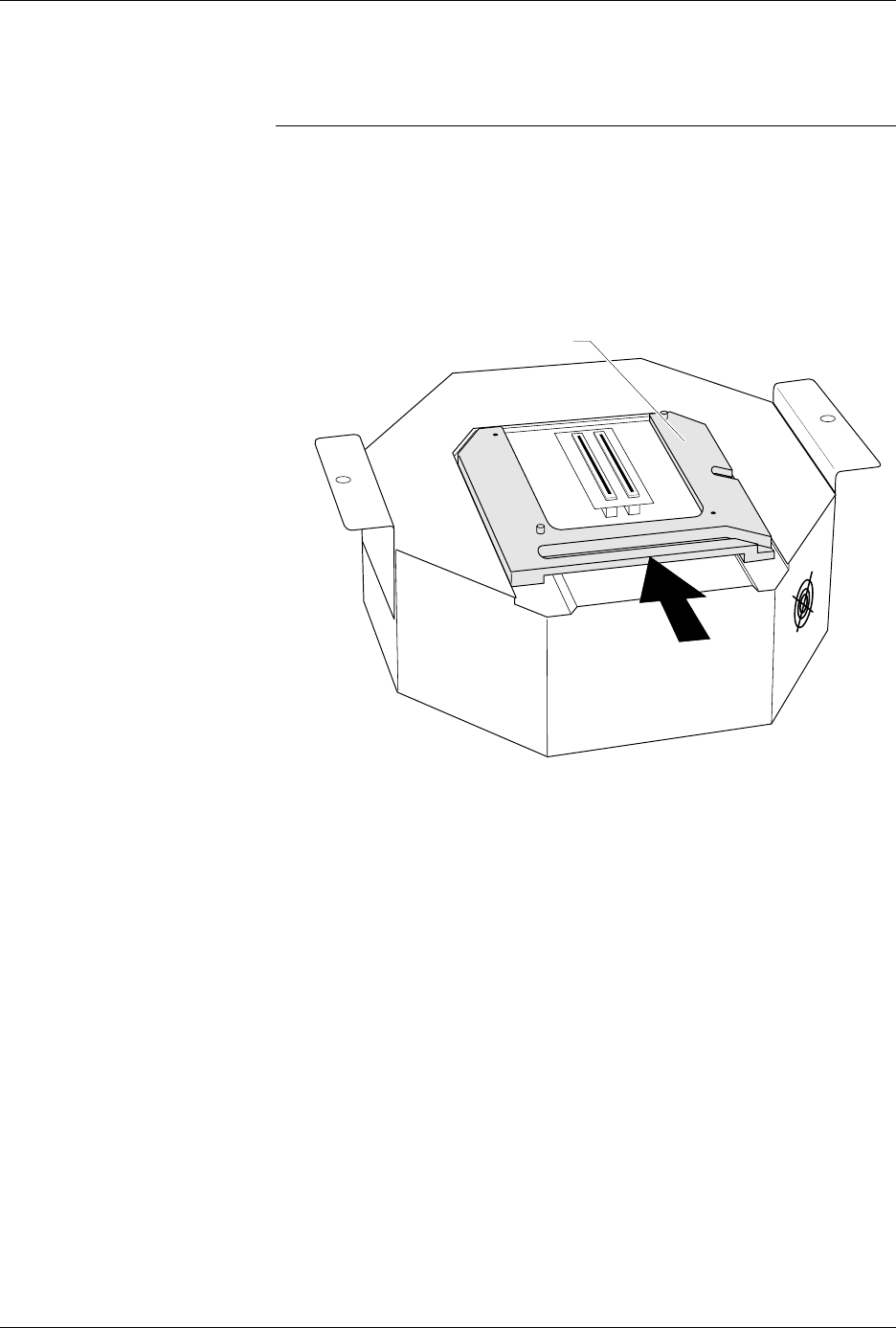
9. As shown in Figure 2-10, slide the clamp ring onto the pin driver
head, securing the programming module in place.
CAUTION: You may have to push down on the programming module
while sliding the clamp ring onto the pin driver head.
Do not use the device socket on the programming module as
a leverage point. You can damage the device socket by
applying any sort of force to it.
You will feel and hear a “click” from the clamp ring when the
programming module is properly secured to the pin driver head.
Figure 2-10
Securing a Programming Module
to the Pin Driver Head
1351-2
PROGRAMMING MODULE CLAMP RING
Setup and Installation
AutoSite User Manual 2-11
Attaching the Pin
Driver Head
Connect the pin driver head to the 2000 as follows:
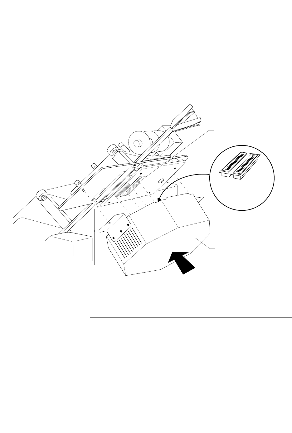
10. Position the pin driver head against the 2000 so the handle on the
clamp ring points toward the top of the 2000.
11. Align the card edge on the contactor set with the card edge
connectors on the programming module. Gently push the pin driver
head onto the 2000.
12. Tighten the thumbscrews on the pin driver head mounting plate,
securing the pin driver head to the Handler. You might have to use a
flatblade screwdriver to finish tightening the thumbscrews.
CAUTION: To prevent damage to the edge connectors, and to ensure
solid contact, we suggest you alternate tightening the left
and right thumbscrews until the pin driver head is
completely fastened to the handler.
13.
(For control units and pin driver heads without connector brackets at ports
J1 and J2)
Connect the 50-pin cable, and the 68-pin cable to the
AutoSite control unit and the pin driver head. The 50-pin cable and
68-pin cable and the ports to which they connect are shown in Figures
1-1 and 1-3.
Figure 2-11
Securing the Pin Driver Head to the ProMaster 2000
1402-2
CARD EDGE ON
CONTACTOR SET
PIN DRIVER HEAD
(clamp ring toward top)
CARD EDGE
CONNECTORS ON
PROGRAMMING
MODULE