Autosite_Users_Manual.pdf - 第50页
Setup and Ins tallation 2-28 Auto Site Us er Man ual The Algorith m disks contain all the programming algorith ms for the devices currently supported by AutoSite. If you have a hard drive (also known as a Mass Storage Mo…
Setup and Installation
AutoSite User Manual 2-27
Power Up AutoSite
Safety Information
This information is provided as a supplement to the Safety Summary at
the beginning of this manual.
The circuitry housed inside the pin driver head and the control unit, and
the devices AutoSite programs are static sensitive and can be damaged by
electrostatic discharge (ESD). To help minimize the effects of ESD, we
suggest you wear an antistatic wrist strap while you follow the
procedures described in this section.
For best performance, the antistatic wrist strap should be connected to a
properly grounded antistatic workstation and the wrist strap should
contain a 1M
Ω
(minimum) to 10M
Ω
(maximum) isolating resistor. We
suggest you connect your antistatic wrist strap to the grounding terminal
on the front of the AutoSite control unit. The grounding terminal is
shown in Figure 1-2.
About the
Programmer Disks
The disk labeled
Boot Files
contains the AutoSite operating system. The
disk must be in the disk drive when you boot AutoSite.
Any disk labeled
System Files
contains the system files necessary for
many operations after the programmer has booted. If prompted to insert
the System Files disk, you can insert any one of the disks labeled “System
Files.”
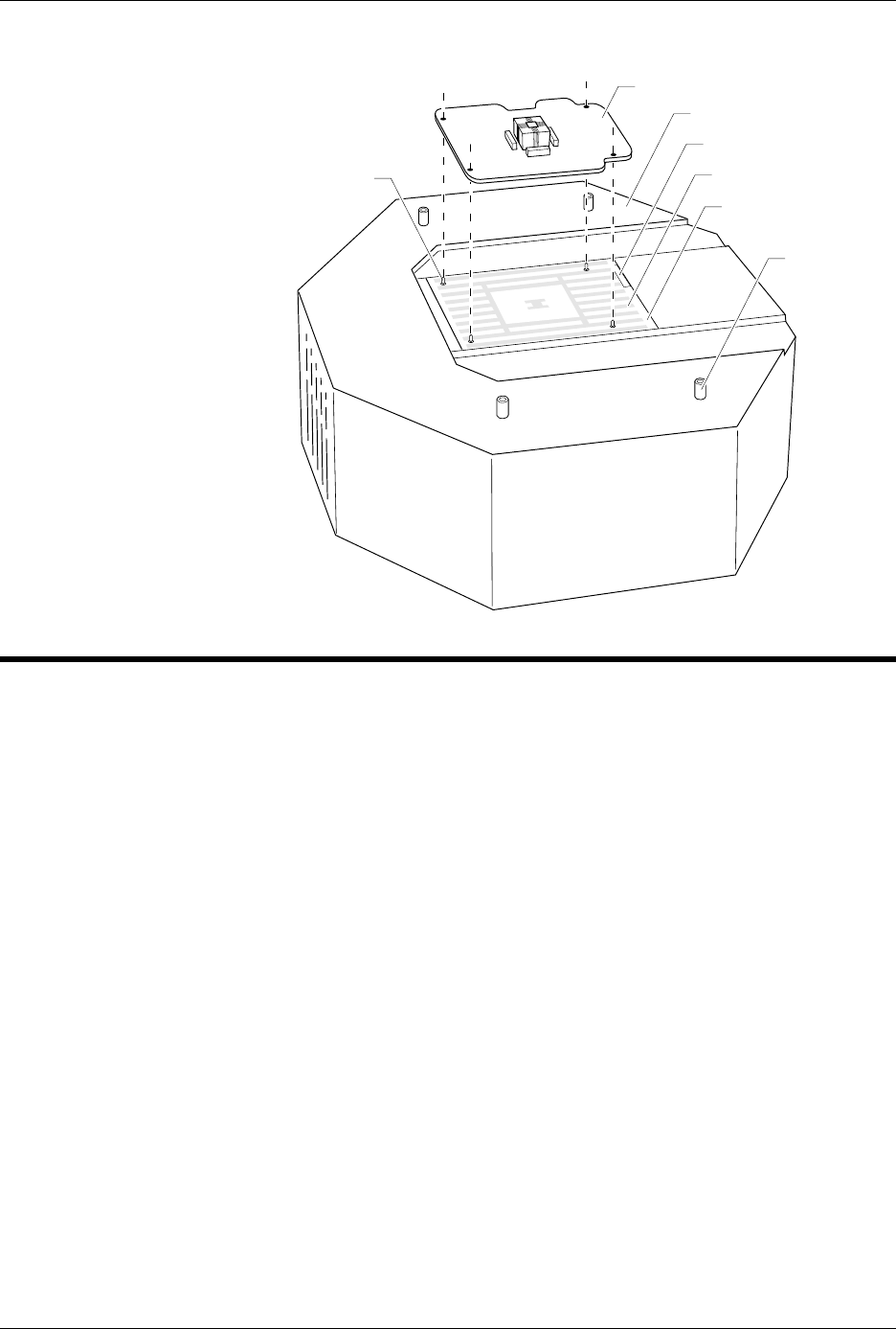
Figure 2-22
Aligning a Programming Module
to the Pin Driver Head
2627-1
PROGRAMMING MODULE
GUIDE PIN
(1 of 4)
PIN DRIVER HEAD
SPA BLOCK
SQUIRT PINS
PART NUMBER LABEL
STANDOFF
(1 of 4)

Setup and Installation
2-28 AutoSite User Manual
The
Algorithm
disks contain all the programming algorithms for the
devices currently supported by AutoSite.
If you have a hard drive (also known as a Mass Storage Module, or MSM)
installed in your AutoSite, you can boot directly from the hard drive after
you install the system and algorithm files on the hard drive. Ensure that
no disks are in the floppy drive when you boot up.
Note: Do not attempt to use the Boot Files disk or the Algorithm disks with more
than one AutoSite. Each disk is intended to work with only one particular
AutoSite.
Once you get AutoSite working, make a backup copy of each disk. The
“Finish Up” section of this chapter describes how to make a backup copies
of the AutoSite disks.
Power Up AutoSite
To power up AutoSite, follow the steps below.
1. Connect one end of the ac line cord to the ac receptacle on the rear
panel of AutoSite and the other end to a properly grounded ac outlet.
AutoSite contains a switching power supply that configures itself to
operate on the proper voltage. The power supply accepts voltages
ranging from 90 to 264 Vac and frequencies ranging from 48 to 63 Hz.
WARNING: To ensure proper grounding, and to avoid the hazard of
electrical shock, connect AutoSite to ONLY a properly
grounded ac outlet.
2. Make sure a programming module (or Base) is installed in AutoSite.
Also, make sure the device socket in the programming module (or
Base) is empty.
CAUTION: Leaving a device in the socket during powerup could damage
the device.
3. Power up the handler.
4. Power up the PC you will use to control AutoSite. Start the
programmer control software, such as TaskLink, you will use to
control AutoSite or start the handler control software you will use to
control AutoSite.
5. If you do not have an MSM, insert the Boot Files disk into the
AutoSite disk drive.
6. Power up AutoSite. The power switch is located on the back panel of
the control unit, next to the ac receptacle, and is pictured in
Figure 1-3.
When you turn the power switch on, the Power LED should light. If it
doesn’t, turn AutoSite off, check the power connections, and turn
AutoSite on again.
Note: Do not remove the Boot Files disk while either the Self Test or disk drive
LED is lit. If you remove the Boot Files disk during powerup, you will
need to reboot AutoSite.

Setup and Installation
AutoSite User Manual 2-29
Did AutoSite Pass
Self-test?
While powering up, AutoSite performs a powerup self-test. AutoSite has
completed powerup when the self-test LED and disk drive LED are off.
Note: The powerup self-test takes approximately three minutes on a 44-pin
AutoSite and four minutes on an 88-pin AutoSite.
If the self-test LED goes off, the power-up self-test did not detect any
system problems. Go to the “Are the Right LEDs Lit?” section.
If the power-up self-test detected anything wrong, the four LEDs on the
front panel of the control unit illuminate in different patterns, telling you
what the self-test found. The different combinations of blinking LEDs are
explained below.
Note: X = don’t care condition.
------------------Indicator------------------
Power Auxiliary Handler
Self-
Test
Description
On Off Off On Self-test in progress. No
Error condition.
On On Off Off Handler port OK; self-
test finished. No Error
condition.
On Off On Off Auxiliary and Handler
ports OK; self-test
finished. No Error
condition.
On On On Off Auxiliary and Handler
ports OK; self-test
finished. No Error
condition.
Off X X Off Power supply problem
On Blinking X On CPU or EPROM problem
or corrupt ID PAL
Off X X On Power supply problem
On Blinking Off On CPU or EPROM problem
On Off Blinking On Bad system RAM
problem
On Blinking Blinking On Serial port DUART
problem
On Blinking Blinking Blinking Power supply problem.
Make sure voltage
selector is set correctly.
X X X Blinking LCA problem