Autosite_Users_Manual.pdf - 第31页
Setup an d Installa tion AutoSite User Manual 2-9 8. Se lect a pr ogra mming module that matc hes th e co ntac tor s et you attached to the pin driver head mo unting plat e in steps 4 and 5. A s shown in Figu re 2-9, set…
Setup and Installation
2-8 AutoSite User Manual
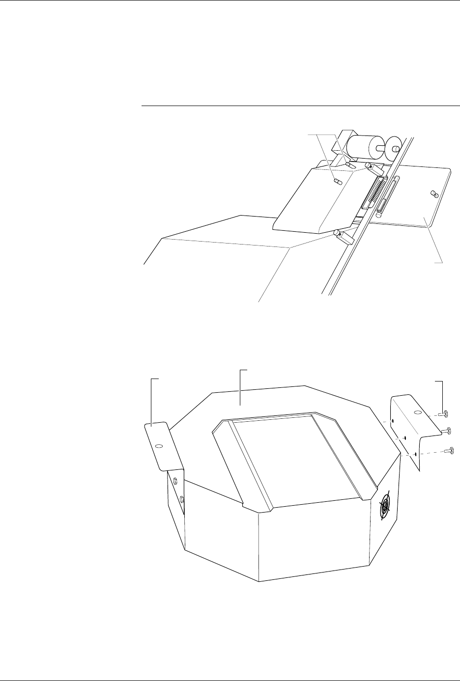
5. Using a 5/32-inch hex driver, secure the contactor set to the pin
driver head mounting plate with the four hex head screws provided.
6. Position the pin driver head mounting plate up to the 2000. Finger
tighten the thumbscrews on the 2000 to secure the pin driver head
mounting plate to the 2000.
CAUTION: Do not touch or damage the gold pins on the contactor set.
7. Using a 5/32-inch hex driver, attach the two mounting brackets to the
pin driver head with the six hex head screws provided. Position the
mounting brackets as shown in Figure 2-8.
Figure 2-7
Attaching the Pin Driver Head
Mounting Plate to the
ProMaster 2000
Figure 2-8
Attaching the Mounting Brackets
to the Pin Driver Head
1346-1
CONTACTOR SET
THUMBSCREWS
1349-1
MOUNTING
BRACKET
(1 of 2)
HEX HEAD SCREW
(1 of 3 per side)
PIN DRIVER HEAD
Setup and Installation
AutoSite User Manual 2-9
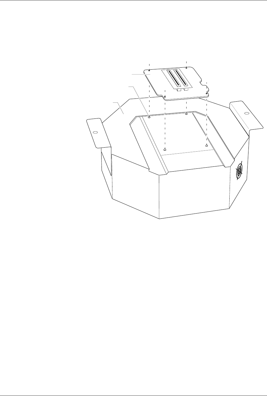
8. Select a programming module that matches the contactor set you
attached to the pin driver head mounting plate in steps 4 and 5. As
shown in Figure 2-9, set the programming module onto the pin driver
head, making sure the guide pins on the pin driver head line up with
the guide holes in the programming module.
Figure 2-9
Aligning the Programming Module
on the Pin Driver Head
1350-1
PROGRAMMING
MODULE
PIN DRIVER
HEAD
GUIDE PIN (1 of 4)
Setup and Installation
2-10 AutoSite User Manual
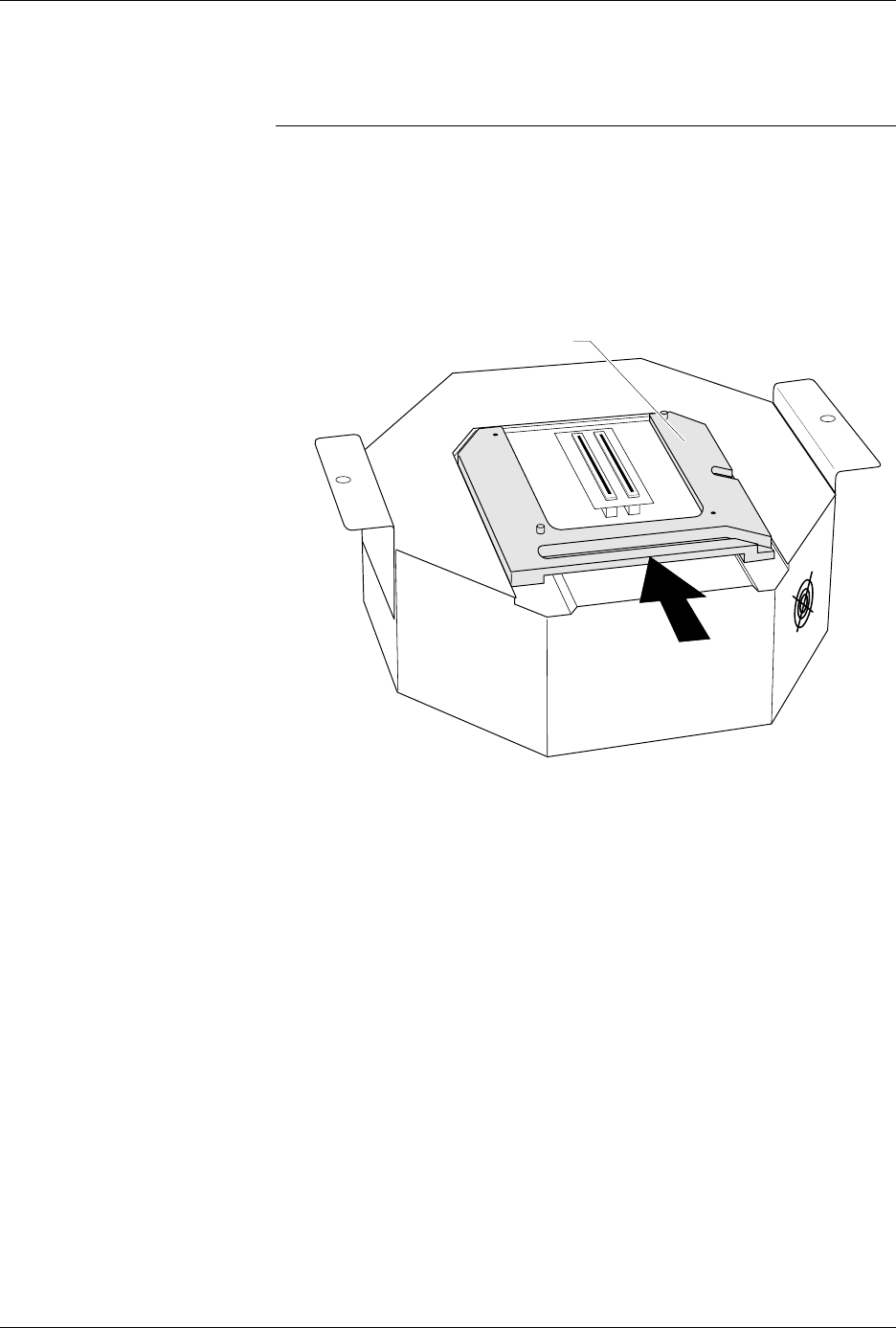
9. As shown in Figure 2-10, slide the clamp ring onto the pin driver
head, securing the programming module in place.
CAUTION: You may have to push down on the programming module
while sliding the clamp ring onto the pin driver head.
Do not use the device socket on the programming module as
a leverage point. You can damage the device socket by
applying any sort of force to it.
You will feel and hear a “click” from the clamp ring when the
programming module is properly secured to the pin driver head.
Figure 2-10
Securing a Programming Module
to the Pin Driver Head
1351-2
PROGRAMMING MODULE CLAMP RING