Autosite_Users_Manual.pdf - 第37页
Setup an d Installa tion AutoSite User Manual 2-15 Figure 2-13 Lower ing the P rogra mmer S helf PROGRAMMING STATION 1407-1 KNOB PROGRAMMER SHELF

Setup and Installation
2-14 AutoSite User Manual
What You Need
In addition to the contents of the Installation Kit, you will need the
following tools and equipment to help you install AutoSite in your
handler.
•Programming module
• Grounded wrist strap
• Antistatic workstation
• 5/32-inch hex driver
• 5/64-inch hex driver
• Flat blade screwdriver
• #2 Phillips screwdriver
• Small wire cutters
Remove the
Programmer Shelf
This section describes how to remove the programmer shelf from the
3000. This section does not apply to a 7000. If you are installing AutoSite
into a 7000, skip to the section titled “Reroute the Optics,” on page 2-17.
CAUTION: In this section, you will be working with the programmer
shelf on the 3000. The shelf is supported by an air shock and
can spring up when you turn the knob or when you detach
the shock from the programmer shelf.
Use caution when adjusting the programmer shelf or
working with the air shock.
1. Power down the handler and the programmer.
2. Loosen the knob on the programmer shelf and push the shelf to its
bottom-most position. Tighten the knob to lock the shelf in place.
3. Remove any programmer, such as an AutoSite, from the programmer
shelf in the handler.
4. Remove any tests sites, programming fixtures, or performance
boards from the programming station on the handler.
5. Remove the metal underplate from the 3000 by lifting the underplate
up and sliding it toward you. Discard the metal underplate; you will
not need it later.
6. Loosen the knob on the programmer shelf and raise the shelf to its
topmost position. Tighten the knob to lock the shelf in place.
Setup and Installation
AutoSite User Manual 2-15
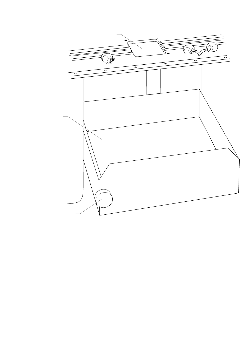
Figure 2-13
Lowering the Programmer Shelf
PROGRAMMING STATION
1407-1
KNOB
PROGRAMMER SHELF
Setup and Installation
2-16 AutoSite User Manual
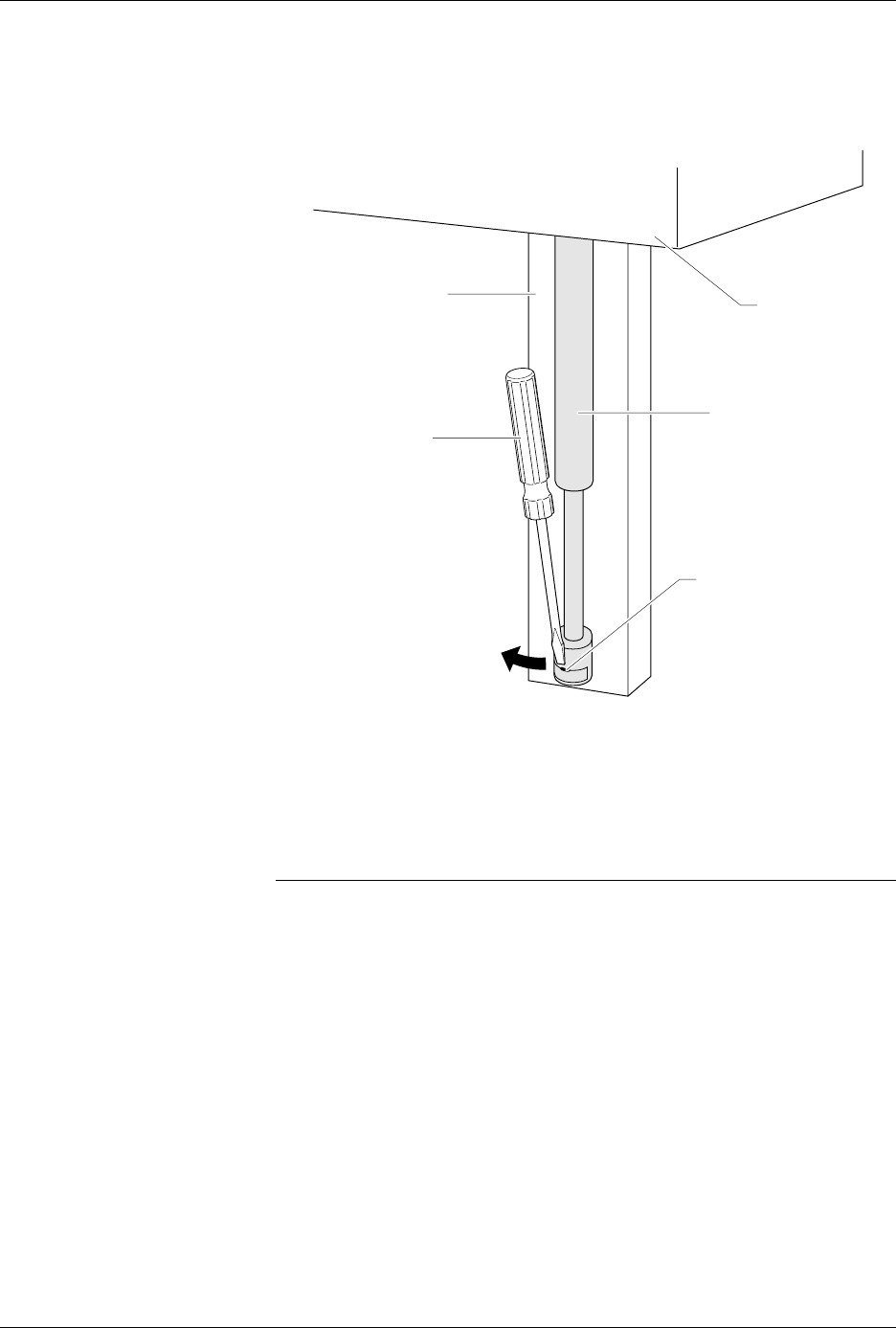
7. Insert a flat blade screwdriver into the notch shown in Figure 2-14.
Disconnect the bottom of the air shock by twisting the blade of the
screwdriver and pulling the bottom of the air shock toward you.
8. Loosen the knob on the programmer shelf and push the programmer
shelf to its bottom-most position.
9. Using a 5/64-inch hex driver, remove the three hex head screws on
the right side of the back of the programmer shelf. Discard these
screws; you will not need them later.
Note: When you remove the last of the three screws, the shelf guide and air shock
assembly will slide off the track.
10. After you have removed all three screws, remove the shelf guide
from the track. Set the shelf guide and the air shock aside; you will
need them later.
11. Remove the knob and shaft from the programmer shelf by turning
the knob counterclockwise. Discard the knob and shaft; you will not
need them later.
Figure 2-14
Disconnecting the Air Shock
1408-2
TRACK
AIR SHOCK
ASSEMBLY
NOTCH
PROGRAMMER
SHELF
SCREW DRIVER