Autosite_Users_Manual.pdf - 第48页
Setup and Ins tallation 2-26 Auto Site Us er Man ual Note : Se e the section in th is chapter titled “Mo re About Ca bles” if yo u are using a serial port wit h nonstandard pinouts or if you want to build y our own seria…

Setup and Installation
AutoSite User Manual 2-25
Connect AutoSite to a Non-ProMaster Handler
This section describes how to connect AutoSite to a handler. The
installation is divided into two main steps:
• Attach the AutoSite control unit to the handler
• Attach the AutoSite pin driver head to the handler
Before you begin, you must set up your handler and install your handler
control software. Refer to the documentation that came with your handler
and handler control software for information.
What You Need
In addition to the contents of the Installation Kit, which is supplied by the
handler manufacturer, you will need the following to connect AutoSite to
a handler:
• Grounded wrist strap
Note: Contact the handler manufacturer if you did not receive hardware for
connecting AutoSite to your handler.
Safety Information
This information is provided as a supplement to the Safety Summary at
the beginning of this manual.
The circuitry housed inside the pin driver head and the control unit, and
the devices AutoSite programs are static sensitive and can be damaged by
electrostatic discharge (ESD). To help minimize the effects of ESD, we
suggest you wear an antistatic wrist strap while you follow the
procedures described in this section.
For best performance, the antistatic wrist strap should be connected to a
properly grounded antistatic workstation and the wrist strap should
contain a 1M
Ω
(minimum) to 10M
Ω
(maximum) isolating resistor. We
suggest you connect your antistatic wrist strap to the grounding terminal
on the front of the AutoSite control unit. The grounding terminal is
shown in Figure 1-2.
Attaching the
Control Unit
Connect the AutoSite control unit to a handler as follows:
1. Verify that the 50-pin cable and the 68-pin cable are connected and
properly fastened to the AutoSite control unit. Do not connect the
other end of the 50-pin and 68-pin cables yet. The 50-pin cable and 68-
pin cable and the ports to which they connect are shown in Figure 1-1
and Figure 1-3.
(For control units without connector brackets at ports J1 and J2.)
The
50-pin and 68-pin cables click when properly connected.
2. If you will be controlling AutoSite from a PC, connect a 25-pin
RS-232C serial cable to the Handler port on the AutoSite control unit.
Refer to Figure 1-3 for the location of the Handler port.
Connect the other end of the serial cable to a serial port on the PC.

Setup and Installation
2-26 AutoSite User Manual
Note: See the section in this chapter titled “More About Cables” if you are using
a serial port with nonstandard pinouts or if you want to build your own
serial cable.
3. Depending on the type of handler you are using, you may be able to
attach the control unit to the handler. Refer to the documentation
provided with your handler for information on connecting the
AutoSite control unit to the handler.
Note: Because of space limitations and other restrictions, you may not be able to
attach AutoSite to some handlers. In this case, simply place the control
unit in a convenient position near the handler. See the handler
documentation for more information.
Connect the Pin
Driver Head
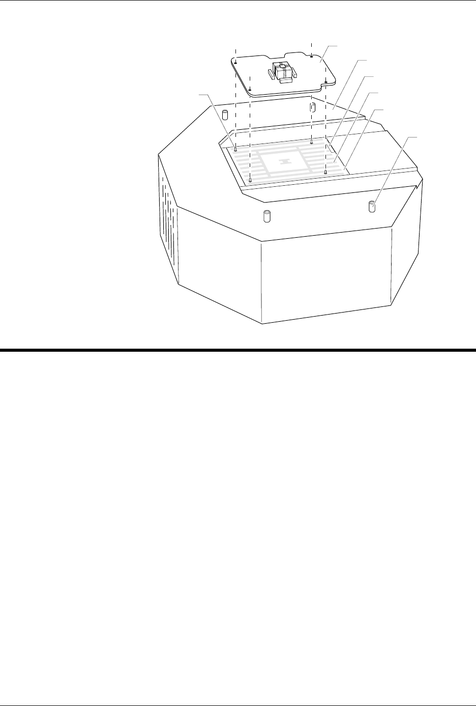
Connect the AutoSite pin driver head as follows:
Note: The four standoffs located around the SPA block on the pin driver head (as
shown in Figure 2-22) may cause interference if the AutoSite is installed
on a non-ProMaster handler. If interference occurs, remove the standoffs
using a 1/4-inch nut driver, or a 1/4-inch open-end box wrench or the
equivalent.
4.
(For pin driver heads without connector brackets at ports J1 and J2.)
Connect the other end of the 50-pin and 68-pin cables to the pin
driver head. The 50-pin and 68-pin cables click when properly
connected to the pin driver head.
(For pin driver heads with connector brackets at ports J1 and J2.)
Remove the two screws that hold the connector shell together at the
unconnected end of the 50-pin cable. Plug the 50-pin cable into the
appropriate port on the pin driver head and fasten it to the connector
bracket by aligning the holes in the bracket with the holes on the
connector shell and reinserting the screws through the holes. Tighten
the screws.
Repeat the procedure for the 68-pin cable.
5. Refer to the documentation shipped with your handler for
information on installing a programming module. We suggest you
keep the following in mind while installing a programming module:
• Make sure the handler is idle
• Wear a properly grounded antistatic wrist strap while working
with the programming module and the pin driver head
• Do not touch the gold pins that are exposed when you remove a
programming module from the pin driver head
• Do not block the fan on the side of the pin driver head
• Make sure the guide pins on the pin driver head line up with the
guide holes in the programming module. See Figure 2-22 for an
example.
• Do not use the device socket or connectors on the programming
module as a leverage point.
Note: The programming module you install may not look like the programming
module shown in Figure 2-22.
Setup and Installation
AutoSite User Manual 2-27
Power Up AutoSite
Safety Information
This information is provided as a supplement to the Safety Summary at
the beginning of this manual.
The circuitry housed inside the pin driver head and the control unit, and
the devices AutoSite programs are static sensitive and can be damaged by
electrostatic discharge (ESD). To help minimize the effects of ESD, we
suggest you wear an antistatic wrist strap while you follow the
procedures described in this section.
For best performance, the antistatic wrist strap should be connected to a
properly grounded antistatic workstation and the wrist strap should
contain a 1M
Ω
(minimum) to 10M
Ω
(maximum) isolating resistor. We
suggest you connect your antistatic wrist strap to the grounding terminal
on the front of the AutoSite control unit. The grounding terminal is
shown in Figure 1-2.
About the
Programmer Disks
The disk labeled
Boot Files
contains the AutoSite operating system. The
disk must be in the disk drive when you boot AutoSite.
Any disk labeled
System Files
contains the system files necessary for
many operations after the programmer has booted. If prompted to insert
the System Files disk, you can insert any one of the disks labeled “System
Files.”
Figure 2-22
Aligning a Programming Module
to the Pin Driver Head
2627-1
PROGRAMMING MODULE
GUIDE PIN
(1 of 4)
PIN DRIVER HEAD
SPA BLOCK
SQUIRT PINS
PART NUMBER LABEL
STANDOFF
(1 of 4)