Autosite_Users_Manual.pdf - 第45页
Setup an d Installa tion AutoSite User Manual 2-23 10. (For pin driver head s without connector brackets at por ts J1 and J2.) Connect the other end of the 50-pin an d 68-pin cables to the pin driver head. The 50-pin and…
Setup and Installation
2-22 AutoSite User Manual
Note: See the section in this chapter titled “More About Cables” if you are using
a serial port with nonstandard pinouts or if you want to build your own
serial cable.
7. If the clamp ring is installed on the pin driver head, slide the clamp
ring off and set it aside; you will need it later. The clamp ring is
shown in Figure 2-10.
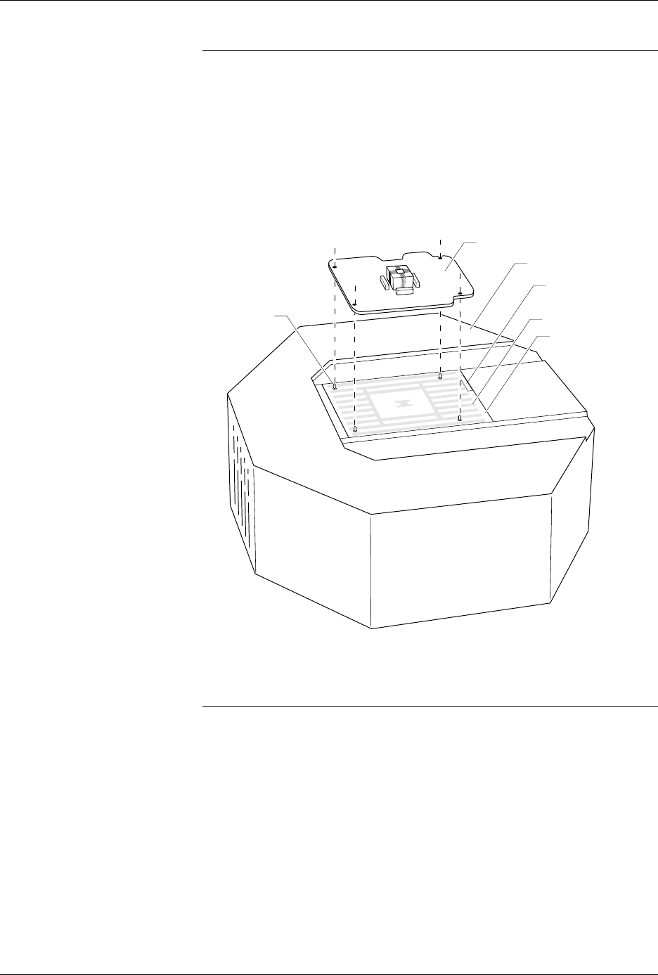
8. As shown in Figure 2-19, set a programming module onto the pin
driver head, making sure the guide pins on the pin driver head line
up with the guide holes in the programming module.
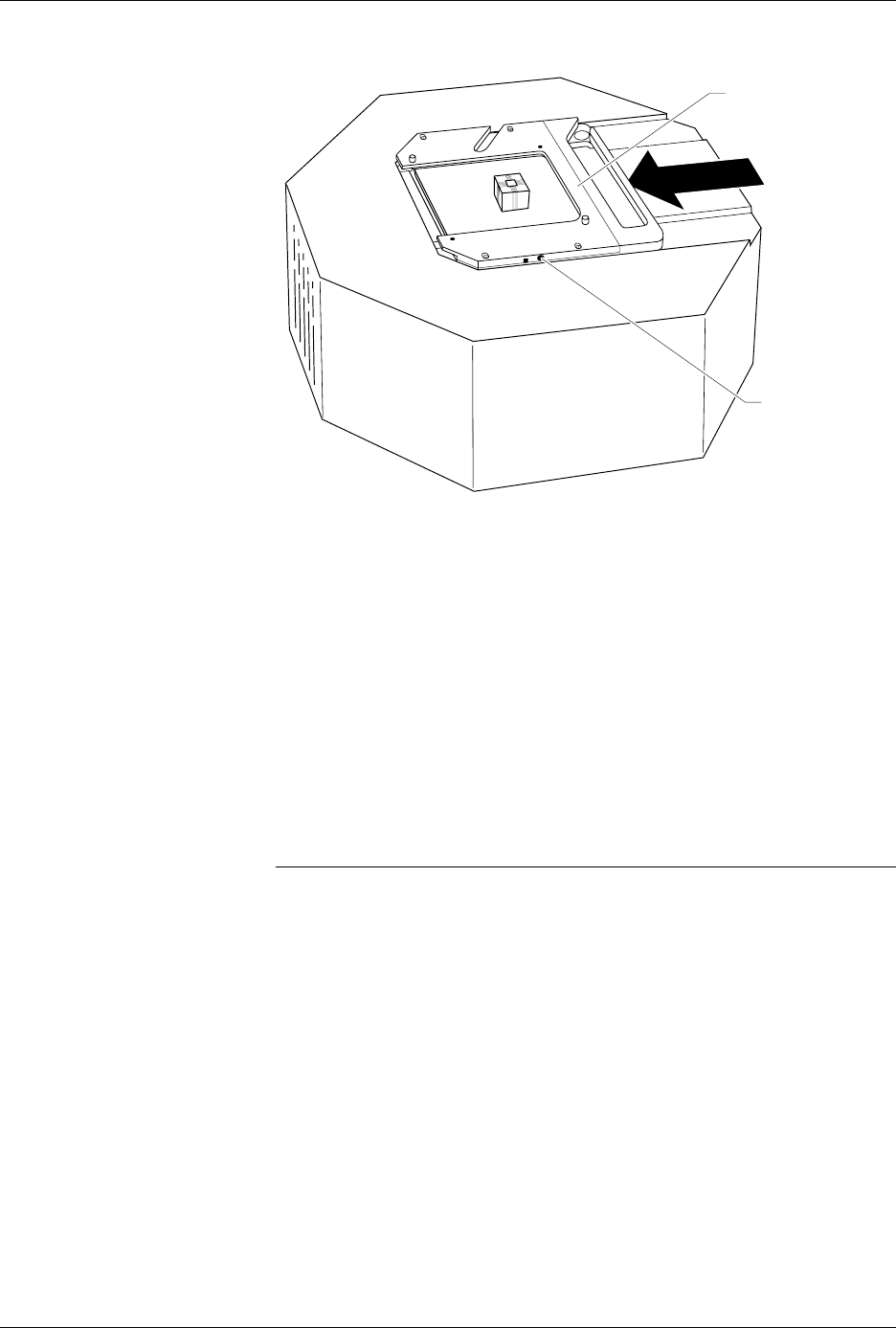
9. As shown in Figure 2-20, slide the clamp ring onto the pin driver
head, securing the new programming module in place.
CAUTION: You may have to push down on the programming module
while sliding the clamp ring onto the pin driver head.
Do not use the device socket on the programming module as
a leverage point. You can damage the device socket by
applying any sort of force to it.
You will feel and hear a “click” from the clamp ring when the
programming module is properly secured to the pin driver head.
Figure 2-19
Aligning a Programming Module
on the Pin Driver Head
1360-3
PROGRAMMING MODULE
GUIDE PIN
(1 of 4)
PIN DRIVER HEAD
SPA BLOCK
SQUIRT PINS
PART NUMBER
LABEL
Setup and Installation
AutoSite User Manual 2-23
10.
(For pin driver heads without connector brackets at ports J1 and J2.)
Connect the other end of the 50-pin and 68-pin cables to the pin
driver head. The 50-pin and 68-pin cables click when properly
connected to the pin driver head.
(For pin driver heads with connector brackets at ports J1 and J2.)
Remove the two screws that hold the connector shell together at the
unconnected end of the 50-pin cable. Plug the 50-pin cable into the
appropriate port on the pin driver head and fasten it to the connector
bracket by aligning the holes in the bracket with the holes on the
connector shell and reinserting the screw through the holes. Tighten
the screws.
Repeat the procedure for the 68-pin cable.
11. Lift up the hood on the handler.
Note: Read the next two steps before proceeding with either step.
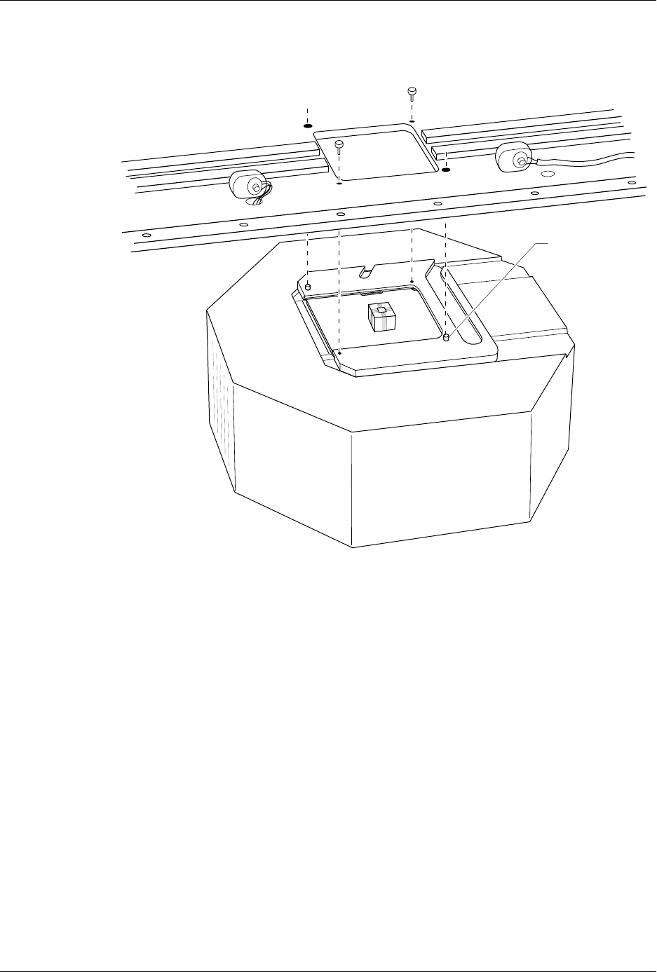
12. Position the pin driver head below the programming station with the
clamp ring to the right. Line up the guide pins on the programming
module with the guide pin holes in the handler.
13. Using the two pin driver head thumbscrews provided, secure the pin
driver head to the handler. See Figure 2-21 for the location of the
holes for the thumbscrews.
Figure 2-20
Securing a Programming Module
to the Pin Driver Head
1361-2
PROGRAMMING
MODULE CLAMP RING
ADJUSTMENT
SCREW
Setup and Installation
2-24 AutoSite User Manual
14. Lower the hood on the handler.
Checking the
Installation
When properly connected to the handler, the clamp ring will be flush
against the handler.
If the clamp ring is not flush against the handler, remove the pin driver
head from the handler and go back to step 8.
You are finished connecting AutoSite to your ProMaster 3000 (or
ProMaster 7000). Go to the section titled “Power Up AutoSite” to
continue with the installation.
Figure 2-21
Securing the Pin Driver Head to the Handler
1362-1
GUIDE PIN
(1 of 2)