Autosite_Users_Manual.pdf - 第76页
Operation 3-18 AutoSite User Manual 4. Insert the de vice into the MatchBo ok, as shown in F igure 3-13. Make sure you insert the device a ccording to the alig nment diagram o n the MatchBoo k. Clos e the Match Book. Not…
Operation
AutoSite User Manual 3-17
Inserting PLCC
Devices and Using
MatchBooks
Read this section if you will be using the Stand Alone Kit (a PLCC Base
and a set of MatchBooks) to program PLCC devices.
Data I/O has developed a new method to accommodate the special
nature of PLCC packages. The method uses the MatchBook, which holds
the PLCC device in place on the PLCC Base. When the device is locked
into place, the conductive pad on the bottom of the PLCC Base forms a
conductive path between the pin drivers in the pin driver head and the
device in the MatchBook.
MatchBooks do away with clumsy and expensive sockets and adapters,
and make inserting and removing surface mount devices much easier
and faster. MatchBooks eliminate the guesswork involved when you
insert a PLCC device into a socket. All you have to do is align pin 1 and
set the device in the MatchBook.
Inserting a Device Into a
MatchBook
The instructions below explain how to use a MatchBook and how to
insert and remove a device from a MatchBook.
1. Insert the PLCC Base into AutoSite. Lock the Base into place. See the
section titled “Inserting the DIP or PLCC Base” for information on
inserting the PLCC Base.
2. Select the MatchBook for the device you are going to use.
3. Insert the MatchBook into the PLCC Base as shown in Figure 3-12.
First, set the front edge of the MatchBook onto the PLCC Base. Then
lower the back edge of the MatchBook into place on the Base.
Figure 3-12
Inserting a MatchBook into the
PLCC Base
0537-3
2
1
FRONT EDGE
(under locking
tabs)
BACK EDGE
LOCKING TAB
Operation
3-18 AutoSite User Manual
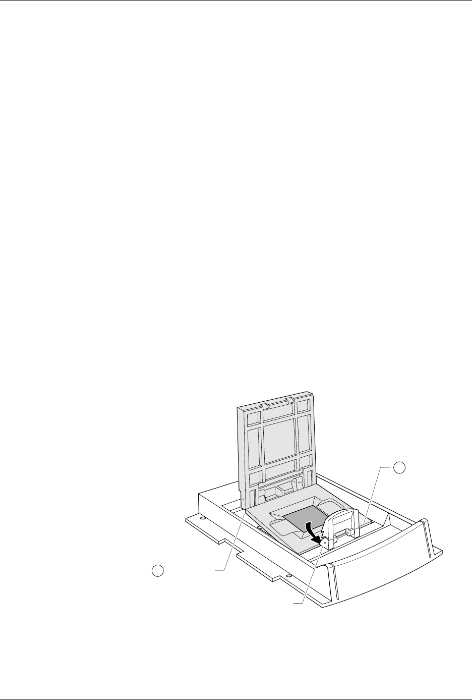
4. Insert the device into the MatchBook, as shown in Figure 3-13. Make
sure you insert the device according to the alignment diagram on the
MatchBook. Close the MatchBook.
Note: Position the device so pin 1 is near to the retaining clip. There is a small
dot molded into each MatchBook to help you align your device. Each
MatchBook also has a beveled corner to help you align devices with a
chamfered corner to indicate pin 1.
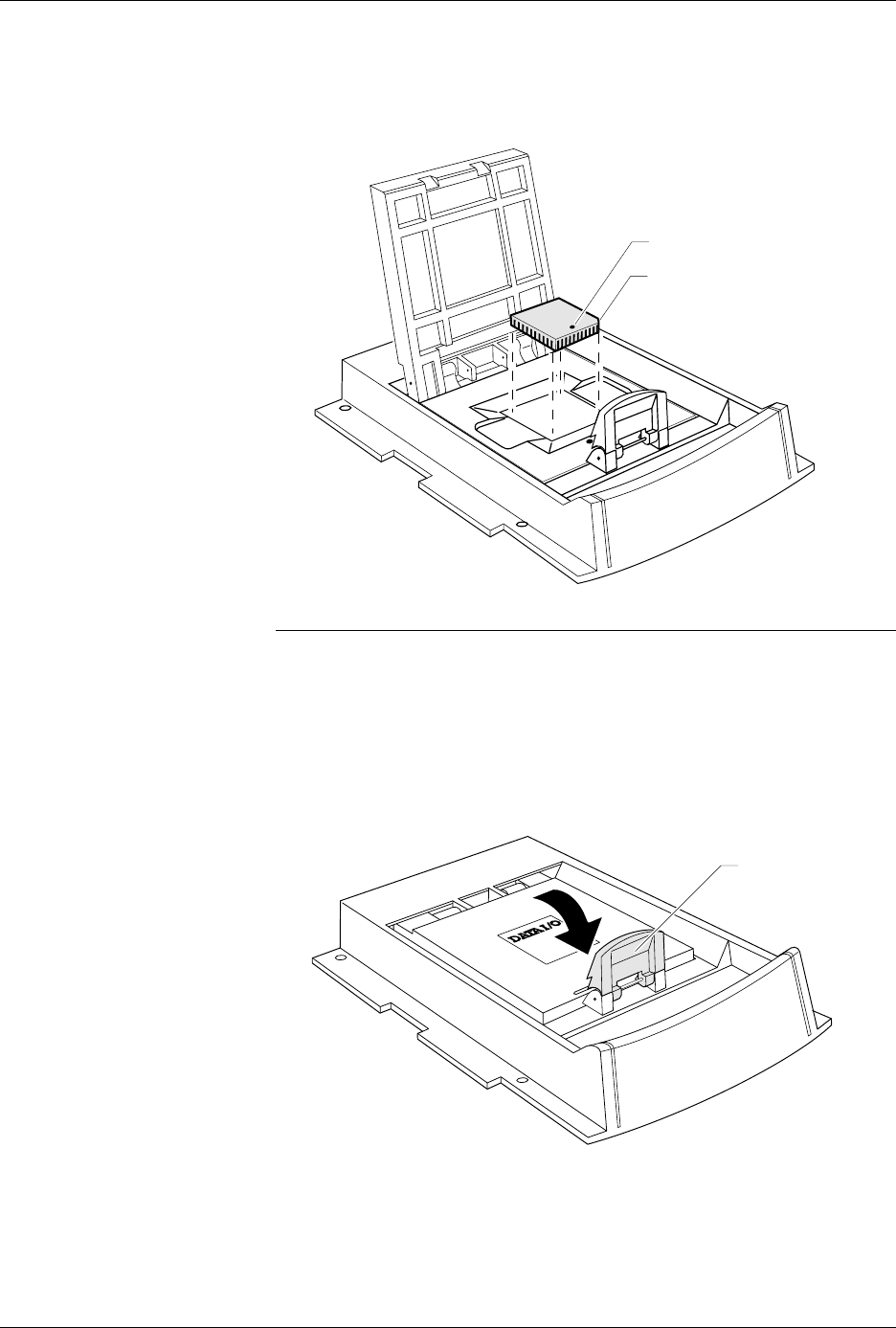
5. Finally, close the MatchBook and press the retaining latch forward
with your thumb until the latch snaps into place, as shown in
Figure 3-14.
Removing a Device
From a MatchBook
To remove a device from the MatchBook, unsnap the retaining latch,
open the MatchBook, and lift out the device.
Figure 3-13
Inserting a Device into the PLCC
Base
Figure 3-14
Closing the MatchBook
0538-3
CHAMFERED
CORNER
PIN 1
0539-4
44 PIN PLCC
RETAINING LATCH

Operation
AutoSite User Manual 3-19
Preventive Maintenance
Conductive Pad
The conductive pad, the material the MatchBook rests on, should be kept
free of dirt to keep yields high and prolong the life of the pad. We
recommend that you inspect and clean the pad at least every 1000 device
insertions or monthly, whichever comes first.
Note: After a number of insertions, you may notice an indentation in the middle
of the conductive pad. The indentation is normal and does not degrade the
contact resistance or the performance of the MatchBook. It is also normal
for the pad to show signs of discoloration as it is used.
The life of the pad is dependent on proper care as well as the pin count
and package type of the device being used. Not all devices have the same
tolerances, and use of each device type may result in different life cycles
for the pad. If you experience an increase in device insertion errors or
continuity errors, or if you experience a sudden drop in programming
yields, the pad may need to be replaced.
Cleaning
Blow air over the pad to clean it. If you use compressed air, direct the air
stream from the front or back of the Base.
Note: To avoid lifting the pad off the circuit board, do not blow air from the side
of the pad.
To further clean the pad, apply a small amount of isopropyl alcohol on a
cotton swab and gently wipe off the pad to dislodge dirt. Make sure the
pad is clear of any cotton filaments left over after cleaning.
CAUTION: Do not clean the pad with any petroleum- or freon-based
products. These substances will cause premature
deterioration of the pad material.
Replacement Pad Kits
The Base has been designed to allow you to replace the pads quickly and
easily and to minimize downtime. To order a replacement pad kit,
contact Data I/O Customer Support as listed in the Preface.
SPA Block and Base
For optimal performance, keep the SPA block (see Figure 3-6) and bases
clean. The following messages during device operations could result
from dirt in the SPA block or base adapter.
ID Error
Continuity Error
Base Adapter not Installed
Device Insertion Error
Overcurrent Error
Base/Adapter Relay Failure
SPA Block Cleaning
To avoid error conditions caused by dirty or worn SPA blocks, we
recommend that you perform the following preventive maintenance
procedures.
• Keep the SPA block covered with a base or programming module
when not in use. To prevent base adapters from contaminating the
SPA block, store them in an uncontaminated area.