Autosite_Users_Manual.pdf - 第64页
Operation 3-6 AutoSite U ser Ma nual 8. Remove the contacto r set from the handler by loos ening the two thumbscrews sh own in Figu re 3-3. Set the contactor set a side. 9. Replace the old contactor set wi th the contact…
Operation
AutoSite User Manual 3-5
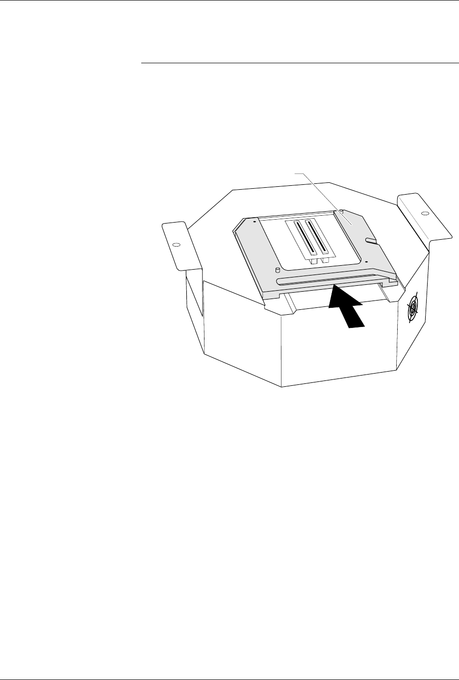
7. As shown in Figure 3-2, slide the clamp ring onto the pin driver head,
securing the programming module in place.
CAUTION: You may have to push down on the programming module
while sliding the clamp ring onto the pin driver head.
Do not use the device socket on the programming module as
a leverage point. You can damage the device socket by
applying any sort of force to it.
You will feel and hear a “click” from the clamp ring when the
programming module is properly secured to the pin driver head.
Figure 3-2
Securing a Programming Module
to the ProMaster 2000
1351-2
PROGRAMMING MODULE CLAMP RING
Operation
3-6 AutoSite User Manual
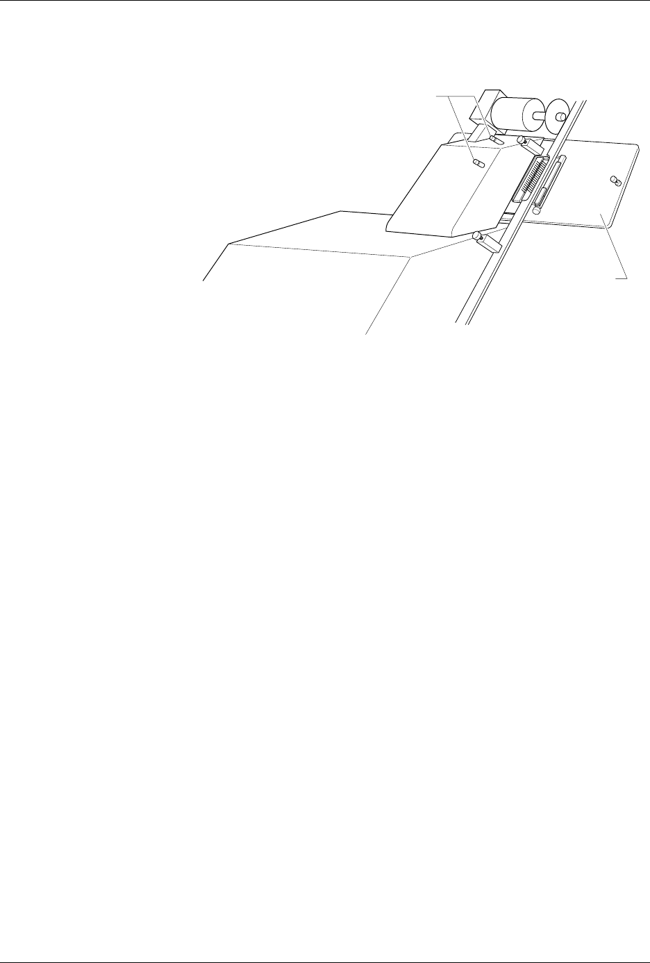
8. Remove the contactor set from the handler by loosening the two
thumbscrews shown in Figure 3-3. Set the contactor set aside.
9. Replace the old contactor set with the contactor set that matches the
programming module you installed in step 6. Position the pin driver
head mounting plate to the handler. Finger tighten the thumbscrews
on the handler to secure the pin driver head mounting plate to the
handler.
10. Position the pin driver head to the handler so that the handle on the
clamp ring is pointing toward the top of the handler.
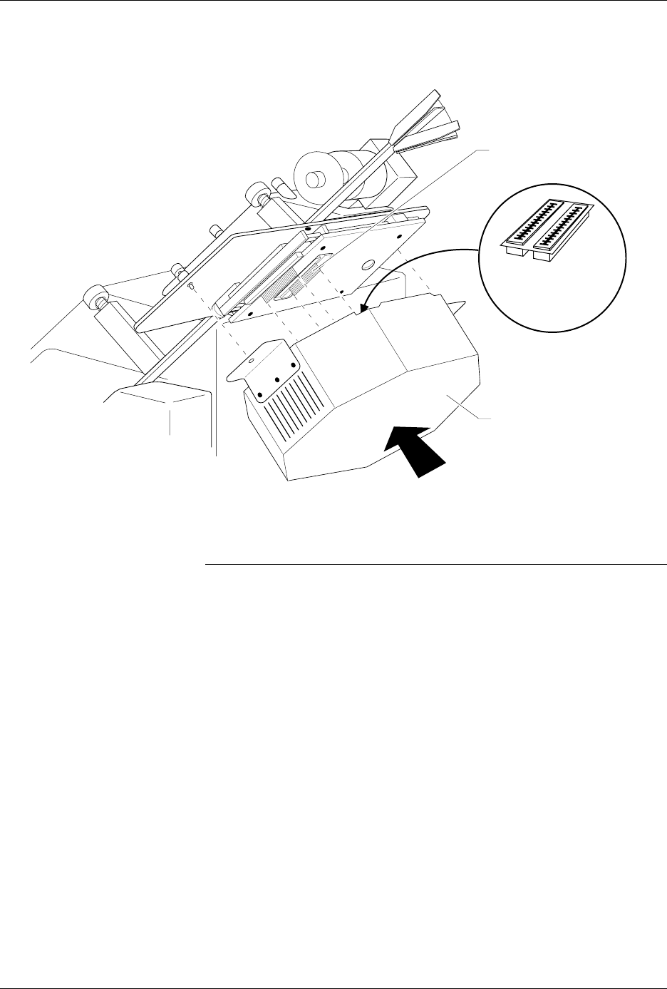
11. As shown in Figure 3-4, align the card edge on the contactor set with
the card edge connectors on the programming module. Gently push
the pin driver head onto the handler.
Figure 3-3
Removing the Contactor Set from
the 2000
1346-1
CONTACTOR SET
THUMBSCREWS
Operation
AutoSite User Manual 3-7
12. Tighten the thumbscrews on the pin driver head mounting plate,
securing the pin driver head to the handler. You might have to use a
flatblade screwdriver to finish tightening the thumbscrews.
CAUTION: To prevent damage to the edge connectors, and to ensure
solid contact, we suggest you alternate tightening the left
and right thumbscrews until the pin driver head is
completely fastened to the 2000.
When properly connected to the handler, the mounting brackets attached
to the pin driver head will be flush against the pin driver head mounting
plate.
You are finished changing the programming module.
Figure 3-4
Aligning the Pin Driver Head with the 2000
1402-2
CARD EDGE ON
CONTACTOR SET
PIN DRIVER HEAD
(clamp ring toward top)
CARD EDGE
CONNECTORS ON
PROGRAMMING
MODULE