IPC9850_Surface Mount Equipment Characterization.pdf - 第12页
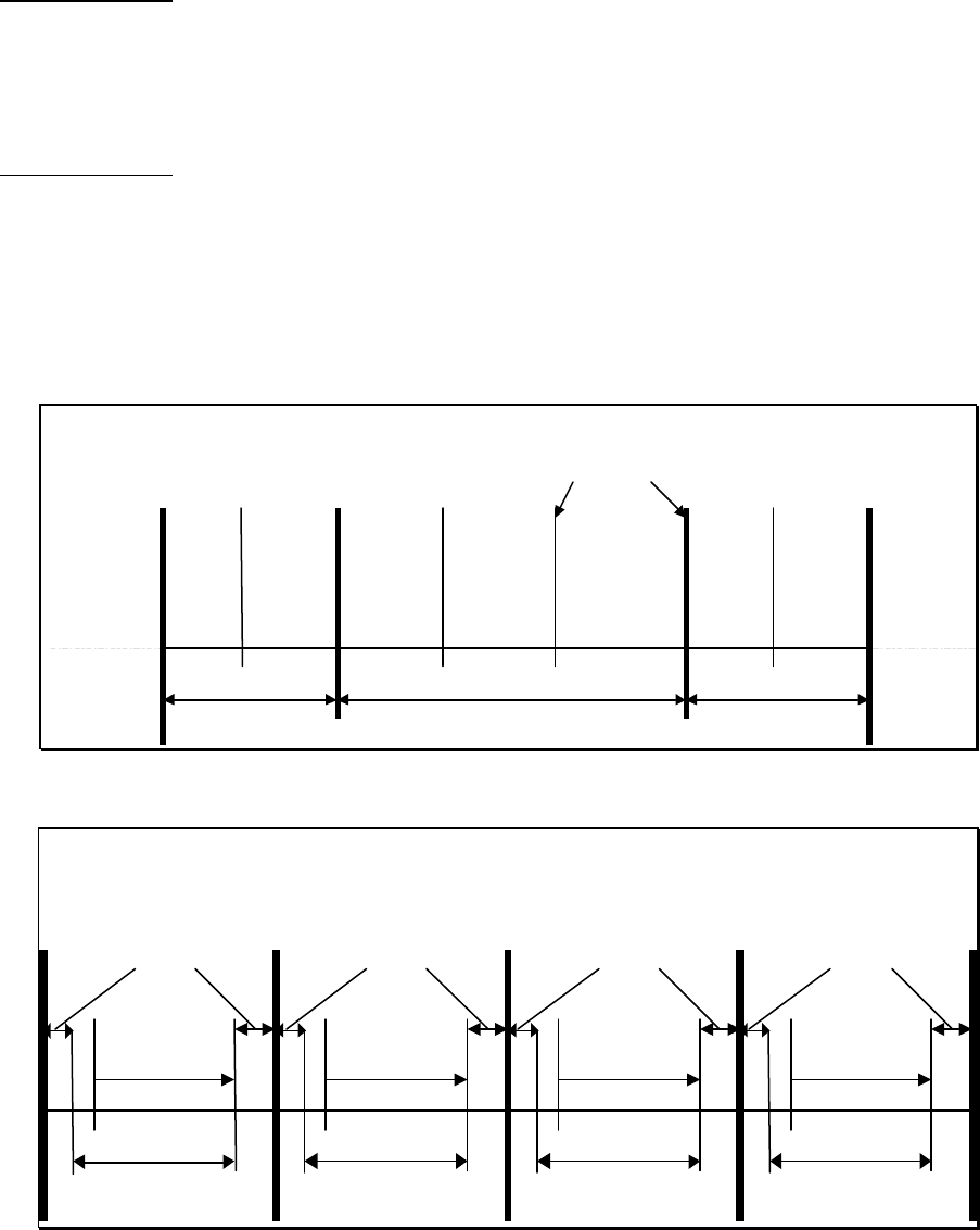
IPC-9850 Official Proposal May 2001 12 Figure 3-2: Performance Parameter Description for a Four-Panel Build These measured parameters -- build time, transfer time and tact time -- must be obtained for the same panel popu…
IPC-9850
Official Proposal
May 2001
11
For this standard, this refers to the number of nozzle utilized by the heads/spindles during the performance
evaluation.
3.3.1.7 Number of Panels Built
For this standard, this refers to the number of panel populated during the evaluation of performance parameters.
Calculation Method - The number of panels is specified in the procedure to be four.
3.3.1.8 Number of Parts Per Panel
For this standard, this refers to the number of components placed on each panel during the evaluation Performance
parameters.
Calculation Method - The number of component placed on each panel is specified by the placement program
corresponding to the specific part type.
3.3.2 Time-Based Parameters
These parameters describe the defined time periods that a board endures during a complete cycle of placing
components on a PWB (glass verification panel in this instance). Figures 3-1 and 3-2 show how these parameters are
defined.
Panel
Transfer
into
Work
Area
Fiducial
Read
Clamping Nozzle
Exchange
Total
Tact
Time
Unclamping
Panel
Transfer
Out of
Work
Area
Movement into
Buffer Zone
Movement
Out of
Buffer Zone
A Single Panel Cycle
Transfer Time Transfer TimeBuild Time
First
placement
Last placement
Figure 3-1: Performance Parameter Description for a Single Panel
A Four Panel Cycle
BuildTime
Total Tact Time
Transfer Time
BuildTime
Total Tact Time
Transfer Time
BuildTime
Total Tact Time
Transfer Time
BuildTime
Total Tact Time
Transfer Time
Panel #1Panel #2Panel #3Panel #4

IPC-9850
Official Proposal
May 2001
12
Figure 3-2: Performance Parameter Description for a Four-Panel Build
These measured parameters -- build time, transfer time and tact time -- must be obtained for the same panel
population build for which the repeatability and accuracy performance values are obtained.
The measurement procedures for these measured time-based parameters require the use of a stopwatch and/or an
oscilloscope. Stopwatches are utilized to measure the duration of a cycle. Oscilloscopes are usually utilized to
monitor hardware transitions in order to identify the start and end of a cycle for transitions that are not be easily (i.e.
repeatable and/or accurately) detectable with the naked eye.
The ability to measure a time-based parameter must be examined by the user to assure that measurements are
precise, i.e. both repeatability and accuracy are acceptable. The stopwatch and/or oscilloscope must have resolution
of at least 0.01 second or better. A GR&R study must be performed to verify that the repeatability of the
measurement is less than 0.01 seconds at a precision/tolerance ratio of better than 25% (see GR&R Discussion
Appendix G)
3.3.2.1 Build Time
Build time for this standard is the average time required to assemble each standard panel. It includes the time
required to align the panels as well as the time to place the components and change nozzles. Build time excludes the
time required to transfer the board into and out of the workstation. Some machines overlap the fiducial alignment
operation with the placement operation. Other machines overlap nozzle changing and pickups with the transfer
operation. The build time ignores these factors.
Measurement Procedure - Use a oscilloscope or stopwatch to measure the amount of time a panel is in the work-
area. Start the timing cycle when the clamp closes. Stop the timing cycle when the clamp opens. Populate four
panels and average the four measurements to obtain the build time.
Calculation Method - Build four panels and average the four measurements to compute the value of the build time
metric.
3.3.2.2 Transfer Time (T
t
)
Transfer time for this standard includes the time required to move the board into the workstation, clamp the board,
release the board and move the board out of the workstation. It represents the overhead associated with transporting
the board when production is flowing normally.
Measurement Procedure - Use a oscilloscope or stopwatch to measure the time from the entry of the first panel to
entry of the fifth panel (not required to be a verification glass verification panel), less the entire Build Time of the
four panels. To minimize measurement error, some easily detectable and clearly defined point in the cycle should be
utilized. Machines that buffer PWB's pre and post population may utilize additional panels to obtain a sustainable
pulse rate, but only the set of four consecutive glass verification panels is acceptable for a proper characterization
procedure.
Calculation Method - Take the time from the entry of the first panel to entry of the fifth panel (not required to be a
verification glass verification panel) minus the entire build time of the four panels divided by four to compute the
transfer time.
3.3.2.3 Total Tact Time
For this standard, Total Tact Time is the required time to place all components on verification glass verification
panels while maintaining the specified placement process capability. It excludes transfer time, fiducial time and
nozzle change time.
Measurement Procedure – Start the oscilloscope or stopwatch to measure the time at which the first component is
placed, and stop the oscilloscope or stopwatch at the time the last component is placed for each of the four panels.
3.3.2.4 Tact Time

IPC-9850
Official Proposal
May 2001
13
For this standard, tact time is the average time required to place each of the standard components at the standard
CAD coordinates on four standard glass verification panels. Tact time excludes the time during which the board is
being moved into position, clamped and aligned as well as the time required for the machine to change nozzles. The
standard CAD coordinates cause the machines to place components across the surface of a 200-mm2 board and
preclude tact times where components are placed artificially close together to minimize motion time. To the extent
that a machine is able to overlap pickup operations with board transfer operations, the tact time of this standard is
somewhat optimistic. This standard permits the supplier to define the feeder configuration and the pick and place
sequence used during the measurement. The number of feeders and heads are reported so the reviewers of the
standard tact time data understand the conditions required to attain it. The tact time is measured during the same
runs used to gather the process capability data. This ensures that placement process parameters are optimized to
achieve the best balance of speed and accuracy.
Calculation Method - Average the four total tact time measurements and divide by the number of components minus
one on a single panel to compute the tact time.
3.3.2.5 Net Throughput
For this standard, it is the number of components per hour (CPH) the machine can place on the verification PVPl.
This definition is implemented to provide a measure of equipment capability in a term that is common in the
industry. Although the value obtained for this parameters does not correlate to a production PWB throughput (since
each panel only has one type of component), it is a useful parameter for the comparison between equipment types.
Calculation Method – The number of components placed on a single glass verification panel, divided by the sum of
the build time and the transfer time parameters divided by 3600.
Example for QFP-100:
Net Throughput = 36 * 3600
(Build Time + Transfer Time)
3.3.3 CMM Measured Parameters
The following is the measurement procedure utilized for collecting data for repeatability and accuracy. Four
standard panels are treated with adhesive (see Appendix C for guidelines for adhesive application). The four panels
are consecutively populated with the placement program specified for the part type. The panels are then placed on a
capable Optical CMM and the component placement error along the X, Y and θ axes are measured.
The measurement system verification for these parameters is discussed in section Measurement Capability
Evaluation Section 5.
3.3.3.1 Repeatability
For this standard, repeatability is defined as one standard deviation of the placement error when placing multiple
components upon multiple PVPs. A deviation is defined as the placement error experienced when the machine
places a component. The placement error is defined as the distance between the actual center location of the
component to the specified CAD location with reference to the board fiducials. Appendix D provides a guide for two
possible methods of measuring the center locations of the components. The errors are defined where Xdev refers to
the placement error in the x-direction. For use of this document, the x-direction is defined as parallel to, and the y-
direction is perpendicular to, the lettering on the placement verification panel . θdev refers to the rotational
placement error (about the component’s X-Y area centroid).