IPC9850_Surface Mount Equipment Characterization.pdf - 第47页
IPC-9850 Official Proposal May 2001 47 Method 2 The leads of the SOIC16 component are measured as follows. The right, left and bottom sides of the lead are measured. Two intersection points are constructed from these mea…
IPC-9850
Official Proposal
May 2001
46
In formulas:
( ) ( )
2
tantan
2
90
4
4
4321
4321
4132
4132
11
21
4321
4321
yyyy
xxxx
xxxx
yyyy
lineline
component
component
component
thetatheta
theta
yyyy
y
xxxx
x
−−+
−−+
−
−−+
−−+
−
+
=
−+
=
+++
=
+
+
+
=
D-3 1608C component
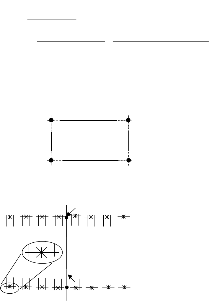
The methods to measure the 1608C component are almost the same as is described for the slugs.
First all four sides of the component are measured (black lines). With these lines, the intersection points are
constructed (black points). Now the same methods as described for the 4 fiducials of the slugs can be applied.
Therefore also for the 1608C component it is recommended to use method 1 and 5 for the component- x, y and theta
respectively.
D-4 SOIC16 component
Method 1
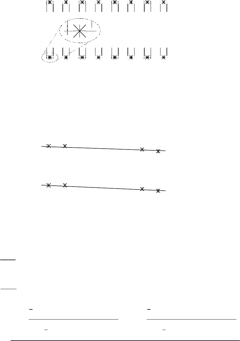
The leads of the SOIC-16 component are measured as follows. The right, left and bottom sides of the lead are
measured. Two intersection points are constructed from these measurements. The average x and y of intersection
points are the coordinates of the lead.
This can be done for all leads, but also for only a few leads. In the section below, measurements are simulated to
determine the influence of the number of measured leads on the center-estimate of the component. Notice that
always the most outer leads are measured to get a correct and reliable calculation of the x,y and angle (e.g. Using 8
leads, at both sides the two outer leads are measured).
The position of the center of the component is the average x and y of all measured leads.
The theta of the component is
1, Average the location for both X
T
and Y
T
on the top side leads of the component
2, Average the location for both X
B
and Y
B
on the bottom side leads of the component
3. Use the points (X
T
,Y
T
) and (X
B
,Y
B
) to determine a line
4, Then measure the angle of this line minus 90 degrees to determine the angle of the component.
3
7 11 15
16
12 8
4
1
5
9
13 14 10
6 2
B
T
IPC-9850
Official Proposal
May 2001
47
Method 2
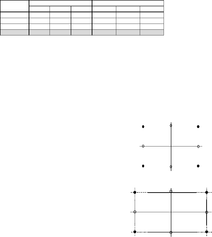
The leads of the SOIC16 component are measured as follows. The right, left and bottom sides of the lead are
measured. Two intersection points are constructed from these measurements. The average x and y of those
intersection points are the coordinates of the lead.
This can be done for all leads, but also for only a few leads. In the section below, measurements are simulated to
determine the influence of the number of measured leads on the center-estimate location of the component. Notice
that always the most outer leads are measured to get a correct and reliable calculation of the x,y and theta location
(e.g. Using 8 leads, at both sides the two outer leads are measured).
The position of the center location of the component is the average X- and Y-location of all measured leads. The
theta of the component is determined by fitting a line through the leads at the north side and one through the leads at
the south side. The average angle of those two lines is the estimated theta location of the component.
In formulas:
2
leadsnorth leadsnorth
2
2
leadsnorth leadsnorth leadsnorth
2
1
leadssouth leadssouth
2
2
leadssouth leadssouth leadssouth
2
1
1
1
tantan
−
−
+
−
−
=
=
=
∑∑
∑ ∑∑
∑∑
∑ ∑∑
∑
∑
−−
=
=
ii
n
iiii
n
ii
n
iiii
n
comp
n
i
i
comp
n
i
i
comp
xx
yxyx
xx
yxyx
theta
n
y
y
n
x
x
1
5
9
13
14
10
6
2
4
8
12
16
15
11
7
3
IPC-9850
Official Proposal
May 2001
48
D-4.1 Simulation
The variation on the intersection points of the leads comes from two error causes:
1. The measurement error, distribution assumed with stdev of 0.0005
2. The component variation, distribution assumed with stdev of 0.0017 in x and 0.0127 in y
With these estimates of the intersection points the lead location is calculated. And with those leads, the center- and
angle location of the component is estimated, using 4,8,12 or 16 leads.
In this way ten thousand measurements are simulated. In the table below are given the estimates of the center- and
angle location of the component using 4,8,12 or 16 leads.
Mean StdevNr. of leads
used x y theta x y theta
4 0.000 0.000 0.000 0.0014 0.0081 1.0325
8 0.000 0.000 0.005 0.0010 0.0057 0.8420
12 0.000 0.000 0.000 0.0008 0.0047 0.8028
16 0.000 0.000 0.001 0.0007 0.0040 0.7989
Table D-3: Mean and stdev vs. nr. of measured leads (nominal means are: x=0, y=0, theta=0)
D-4.2 Conclusion
From the results above, can be concluded that using all 16 leads, gives the best estimate of the center- and angle
location of the component.
D-5 Recommendations
The results in this report show that the way the center- and angle location of a component are measured influences
the accuracy. Therefore it is recommended to include general directions for measuring the components which are
used in the IPC-9850 standard.
In the figures below, the measurement recommendations given in this Appendix are summarized.
Glass QFP-100, QFP-208 and BGA-228
Measure the fiducials (1,2,3,4)
Construct intersection points (A,B,C,D)
x,y: Average of x resp. y of the fiducials (1,2,3,4)
theta: Average angle of lines AC and BD
1608C
Measure sides of component (thick lines)
Construct intersection points (1,2,3,4)
Calculate midpoints (A,B,C,D)
x,y: Average of x resp. y of the fiducials (1,2,3,4)
theta: Average angle of lines AC and BD
2
A
3
4
C
D B
1
2A
3
4 C
D B
1