IPC9850_Surface Mount Equipment Characterization.pdf - 第28页
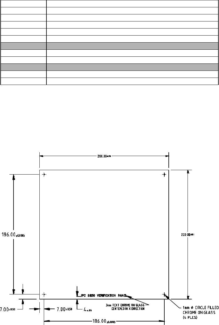
IPC-9850 Official Proposal May 2001 28 Figure 6-1 Placement Verification Panel 6.2 Placement Verification Panel Carrier Specifications The standard does not specify or require the use of a carrier for the PVP. A recommen…
IPC-9850
Official Proposal
May 2001
27
6 Test Vehicles
Users of this standard shall utilize standardized materials and methods to ensure that users and suppliers of SMT
placement equipment are able to observe the same placement performance results within the tolerance of their
measurement gauge’s repeatability, reproducibility and accuracy.
Table 6-1 is the material list for the execution of the placement performance evaluation. Check the IPC website for
suggested suppliers of evaluation material.
Table 6-1 Tool Kit Materials List For Performance Evaluation
Quantity Material
4 Placement Verification Panel (see Figure 6-2)
1 CMM Measurement Verification Panel
150 QFP-100 slugs with no background or with white background
130 QFP-208 slugs with no background or with white background
150 BGA-228 slugs with no background or with white background
1600+ 1608C Components
240+ SOIC 16 Components
Optional
4 PVPl Carrier
- Sticky tape
6.1 Placement Verification Panel Specifications
Glass verification panels with anti-reflective chrome metallization are used because they are dimensionally stable
and can be made very accurately. The glass board fiducials create stable high-contrast images on both placement
machines and CMMs. The transparent glass allows the use of back lighting on the CMM to increase the gauge
repeatability of the measurements.
The IPC-9850-P1 placement verification panel (Figure 6-1) was designed to be small enough to measure on
relatively affordable vision CMMs and large enough to represent a typical sized PWB.
IPC-9850
Official Proposal
May 2001
28
Figure 6-1 Placement Verification Panel
6.2 Placement Verification Panel Carrier Specifications
The standard does not specify or require the use of a carrier for the PVP. A recommended carrier design is shown in
Appendix I.
6.3 Glass Slug Specifications
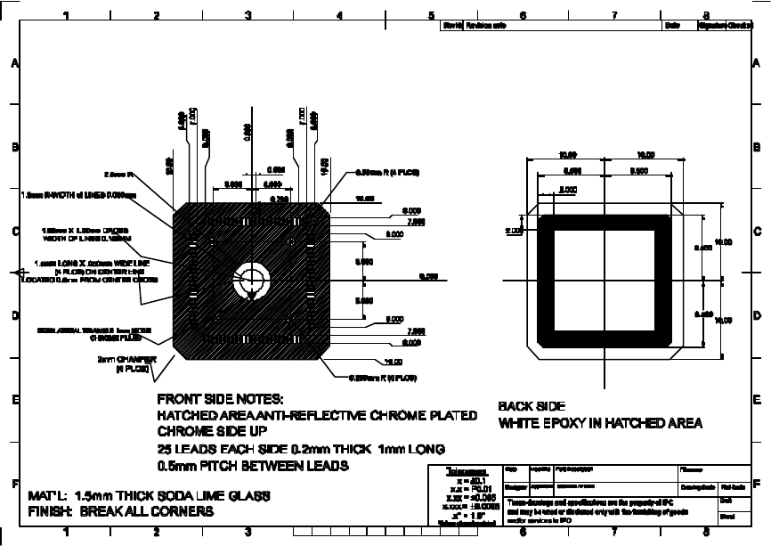
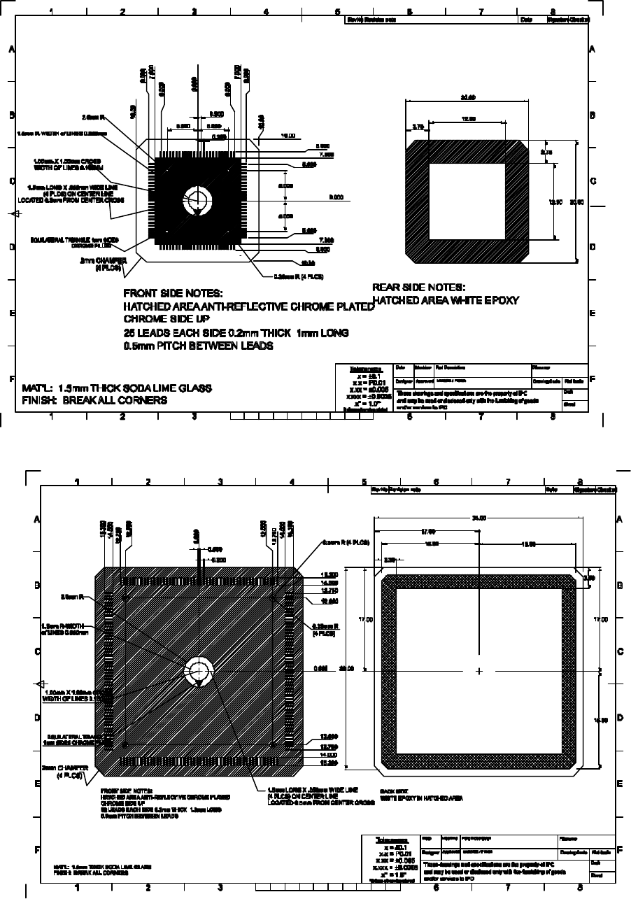
Slugs must meet the dimensional specifications of Figures 6-2, 6-3, 6-4, 6-5, 6-6, and 6-7.
Implication of the glass slug weight on placement acceleration and speed was considered. While there may be cases
where the machine performance will need to be adjusted to accommodate the slug, this type of slugs are currently
being used by most vendors without performance issues.
The patterns on the slugs will be made of black chrome. Since some suppliers use front lighting and some use back
lighting the slugs may be either white background for leads on chrome background or chrome leads with no
background.
Sheet
Material / Finish
Draft
Unless otherwise stated
B
A
1 32 4 5
RevNo
76
B
8
Signature
A
F
1
E
D
C
2 3 6 7 8
E
D
C
F
EQUILATERAL TRIANGLE 1mm SIDES
8.500
8.500
2.000
2.000
5.000
5.000
5.000 5.000
8.500 8.500
WHITE EPOXY IN HATCHED AREA
BACK SIDE
0.000
0.500
0.200
8.000
8.000
6.000
6.000
7.000
7.000
10.00
10.00
10.00 10.00
10.00
10.00
FRONT SIDE NOTES:
HATCHED AREA ANTI-REFLECTIVE CHROME PLATED
25 LEADS EACH SIDE 0.2mm THICK 1mm LONG
CHROME SIDE UP
1.5mm LONG X .050mm WIDE LINE
(4 PLCS) ON CENTER LINE
1.00mm X 1.00mm CROSS
1.5mm R-WIDTH of LINES 0.050mm
0.50mm R (4 PLCS)
’
Figure 6-2 QFP 100 Slug for White Background for Leads on Chrome Background (Negative)
Drawing File Name: ipc_100QFP_glass_NEGATIVErevb.eps
IPC-9850
Official Proposal
May 2001
29
Figure 6-3 QFP 100 Slug for Chrome Leads With No Background (Positive)
Drawing File Name: ipc_100QFP_glass_POSITIVErevb.eps
HATCHED AREA ANTI-REFLECTIVE CHROME PLATED
52 LEADS EACH SIDE 0.2mm THICK 1.3mm LONG
Sheet
Material / Finish
Draft
Unless otherwise stated
WHITE EPOXY IN HATCHED AREA
BACK SIDE
CHROME SIDE UP
B
A
1 32 4 5
RevNo
76
B
8
Signature
A
F
1
E
D
C
2 3 6 7 8
E
D
C
F
’
0.500
0.200
17.00
15.80
17.00
33.00
17.00
15.80
15.80
EQUILATERAL TRIANGLE
1mm SIDES CHROME FILLED
0.000
1.5mm LONG X .050mm WIDE LINE
(4 PLCS) ON CENTER LINE
1.00mm X 1.00mm CROSS
34.00
Table 6-4 QFP 208 Slug for White Background for Leads on Chrome Background (Negative)
Drawing File Name: ipc_QFP208_glass_NEGATIVE.eps
Sheet
Material / Finish
Draft
Unless otherwise stated
B
A
1 32 4 5
RevNo
76
B
8
Signature
A
F
1
E
D
C
2 3 6 7 8
E
D
C
F
EQUILATERAL TRIANGLE 1mm SIDES
5.000
5.000
5.0005.000
20.00
20.00
0.000
0.500
0.200
8.000
8.000
6.000
6.000
7.000
7.000
10.00
10.00
12.50
12.50
FRONT SIDE NOTES:
HATCHED AREA ANTI-REFLECTIVE CHROME PLATED
25 LEADS EACH SIDE 0.2mm THICK 1mm LONG
CHROME SIDE UP
1.5mm LONG X .050mm WIDE LINE
(4 PLCS) ON CENTER LINE
1.00mm X 1.00mm CROSS
1.5mm R-WIDTH of LINES 0.050mm
’
0.25mm R (4 PLCS)