IPC9850_Surface Mount Equipment Characterization.pdf - 第35页
IPC-9850 Official Proposal May 2001 35 6.5.3 QFP-100 and BGA-228 Slugs The panel is populated with glass slugs for the corresponding component type. Fine pitch placement programs for the QFP-100, and BGA-228 have the pos…
IPC-9850
Official Proposal
May 2001
34
6.5.2 SOIC-16 Component
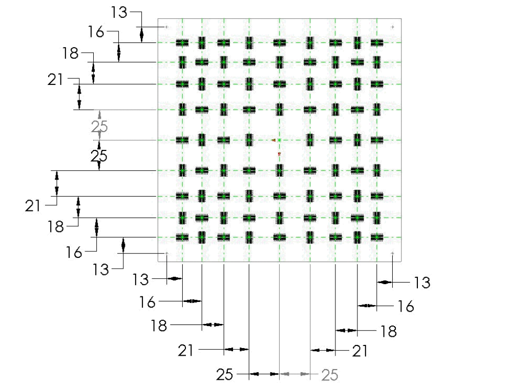
Figure 6-9 presents the placement layout for the SOIC-16 component on the PVP. Appendix E presents the positions
of the components with respect of the fiducials in numeric format.
Figure 6-9 Component Location Layout for SOIC 16 Components
File Name: SOIC-16 Placement Layout.pcx
IPC-9850
Official Proposal
May 2001
35
6.5.3 QFP-100 and BGA-228 Slugs
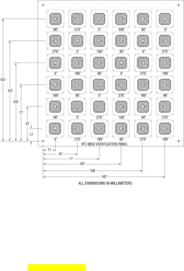
The panel is populated with glass slugs for the corresponding component type. Fine pitch placement programs for
the QFP-100, and BGA-228 have the position and angular rotation pattern shown in Figure 6-10. Appendix E
presents the positions of the components with respect of the fiducials in numeric format.
Figure 6-10 Component Location Layout for QFP-100 and BGA 228 Slug Components
6.5.4 QFP-208 Slug
Figure 6-11 presents the placement layout for the QFP-208 slug component on the PVP. Appendix E presents the
positions of the components with respect of the fiducials in numeric format.
[new drawing pending]
Figure 6-11 Component Location Layout for QFP-208 Slug Components
IPC-9850
Official Proposal
May 2001
36
7 Forms and Diagrams
The forms and diagrams on the following pages may be freely copied and reproduced. Contact IPC for electronic
copies of the forms. [web download after this is published]
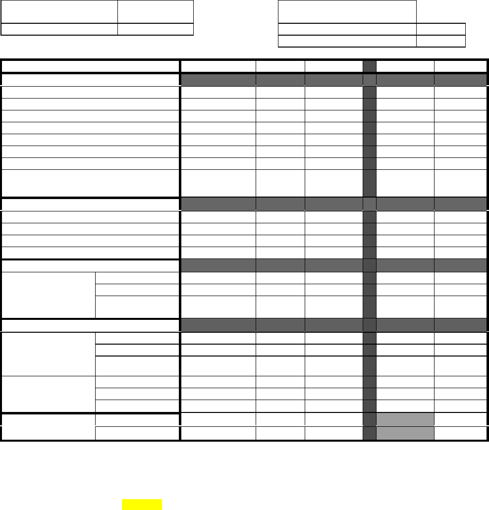
Placement Performance Form
IPC-9850-F1
Manufacturer Name When form is used for ship
verification
Machine Model Serial Number
Build Date and Time
Component Type QFP-100 QFP-255 BGA-228 1608C SOIC-16
Test Conditions During Build
Number of Heads/Spindles
Type of Heads/Spindles
Type of Camera
Number of Feeders/Trays
Type of Nozzles
Number of Nozzles
Number of Panels Built 4 4 4 4 4
Number of Parts Per Panel 36 30 36 400 (120 for
CMM meas.
validation)
80
Test Results
Build Time, seconds
Transfer Time, seconds
Tact Time, seconds
Net Throughput, CPH
Repeatability (One Standard Deviation)
X, micrometers
Y, micrometers
Axis
θ, degrees
Accuracy
+X, micrometers
+Y, micrometers
Spec. Limits
1
for
Cpk=1.33
+θ, degrees
+X, micrometers
+Y, micrometers
Spec. Limits
1
for
Cpk=2.0
+θ, degrees
50% Coverage N/A
2
Cpk for
Termination-to-Land
75% Coverage N/A
2
Note 1 : To be valid, reported Spec. Limits must not exceed the Spec. Limits of the CMM capability reported in
form IPC-9850-F3.
Note 2: Termination-to-Land evaluation for 1608 components is not required. See Section 3.4.3.2.2 for details.
Form 9850-F1 Performance, issue date