IPC9850_Surface Mount Equipment Characterization.pdf - 第31页
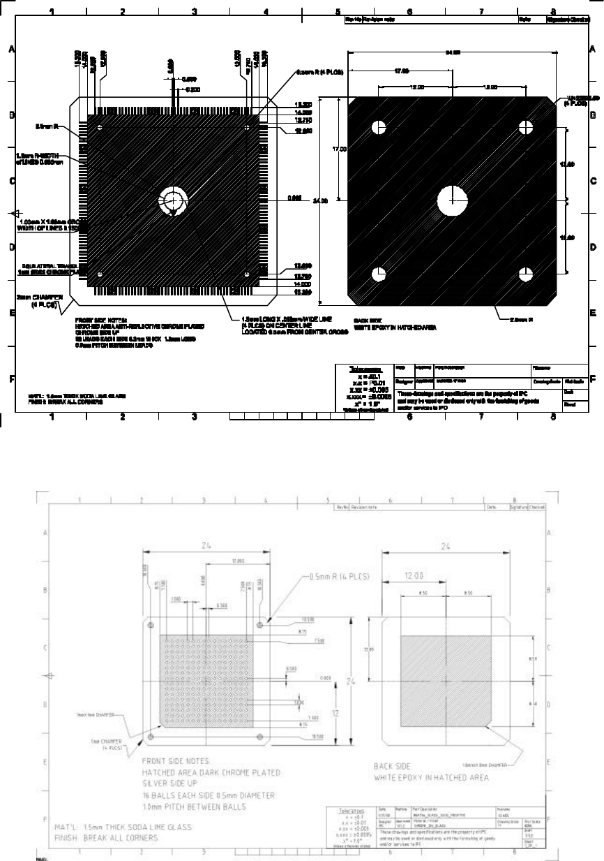
IPC-9850 Official Proposal May 2001 31 Figure 6-7 BGA228 Slug for Chrome Leads With No Background
IPC-9850
Official Proposal
May 2001
30
HATCHED AREA ANTI-REFLECTIVE CHROME PLATED
52 LEADS EACH SIDE 0.2mm THICK 1.3mm LONG
Sheet
Material / Finish
Draft
Unless otherwise stated
WHITE EPOXY IN HATCHED AREA
BACK SIDE
CHROME SIDE UP
B
A
1 32 4 5
RevNo
76
B
8
Signature
A
F
1
E
D
C
2 3 6 7 8
E
D
C
F
’
0.500
0.200
17.00
34.00
EQUILATERAL TRIANGLE
1mm SIDES CHROME FILLED
12.00
12.00
12.00 12.00
17.00
34.00
0.000
1.5mm LONG X .050mm WIDE LINE
(4 PLCS) ON CENTER LINE
1.00mm X 1.00mm CROSS
Table 6-5 QFP 208 Slug for Chrome Leads With No Background (Positive)
Drawing File Name: ipc_QFP208_glass_POSITIVE.eps
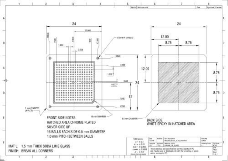
Figure 6-6 BGA228 Slug for White Background for Leads on Chrome Background
IPC-9850
Official Proposal
May 2001
31
Figure 6-7 BGA228 Slug for Chrome Leads With No Background
IPC-9850
Official Proposal
May 2001
32
6.4 Sticky Media Application
To maintain the components in location on the glass panel, a double-sided sticky media adhesive is applied to the
glass verification panel area between the fiducial markings. There are two important requirements for the sticky
media. The first is the consistency by which the sticky material is applied to the glass verification panel surface. It is
important that the adhesive be applied evenly across the entire surface of the glass while providing sufficient clarity
for the CMM back light. The second requirement is the stability of the sticky material once it is applied to the glass
media. The adhesive must maintain the components in position during the placement cycle, where the glass
verification panel may be exposed to rapid accelerations. It must also keep the components in position throughout
the evaluation procedure as time and environmental conditions change from the placement machine location to the
CMM location.
The application of the sticky media to the glass verification panel requires significant care and experience. The
application procedure of the sticky media is not specified (it is not possible to improve test results by improper
application--only worse results). It is left up to the user to determine the proper application of the adhesive.
Details and suggestions are provided in Appendix C.
6.5 Placement Program
6.5.1 1608C Component
The placement layout for 1608C components was designed to exercise the placement machine's capability at placing
components at various distances from each other, so all machine axis are exercised, see Figure 6-8. The components
are placed at the four most common placement angles -- 0, 90, 180 270 degrees -- and the placement order and the
number of supporting feeders is to be determined by each individual machine vendor with the goal of optimizing
placement rate and accuracy for a specific machine type. Appendix E presents the positions of the components with
respect of the fiducials in numeric format.