IPC9850_Surface Mount Equipment Characterization.pdf - 第15页
IPC-9850 Official Proposal May 2001 15 evaluated with mathematical equations that quantify total error, i.e. the combined impacts of the X, Y, and θ deviations. The ‘Termination-to-Land Calculations.xls’ spreadsheet prov…

IPC-9850
Official Proposal
May 2001
14
Calculation Method
The average of the X
dev
’s,
∑
=
=
n
i
i
X
n
X
1
1
, and Standard Deviation of the X
dev
’s,
2
1
)(
1
1
, XX
n
s
n
i
ix
−
−
=
∑
=
,
where i refers to the slug or component number,
X
i
= refers to the x error of the i
th
slug or component,
and n refers to the total number of slugs or components placed over all boards and all locations. Example, when the
placement of QFP-100 or BGA-228 slugs is evaluated, 36 slugs are placed per PVP on a total of 4 panels; thus
n=36*4 = 144.
3.3.3.2 Accuracy
In industry, many suppliers specify performance against their own unique specification limits and capability index
values (e.g. ±40 um with Cpk ≥ 1.5). One of the aspects of this IPC-9850 standard is that, instead of having a
different specification limit and a different sigma level for each supplier, results from each shall be provided in
terms the specification limits required to sustain Cpk’s of 1.33 and 2.0. Specification limits are directly comparable
from one machine to another when machines are reported at the same Cpk levels.
As long as surface mount placement equipment has been on the market, the manufacturers’ claims and guarantees
regarding placement accuracy levels have been cited in terms of X, Y, and θ (rotational) axes, separately. This
traditional method of reporting performance, where performance is considered individually per axis considered, is
covered in Sections 3.4.3.1 and 3.4.3.2.
A relatively recent method that considers the collective effect of all axes is also included in this standard (see
Section 3.4.3.2.2). The essential advantage of this method is that it relates more directly to the soldering process than
the traditional method, because there are combinations of the X, Y, and θ deviations that separately may fall within
spec, but when combined, sometimes prevent the formation of an adequate solder joint.
3.3.3.2.1 Spec limits for Cpk
For this standard, spec limits for Cpk are the specification limits for which the machine is capable of placing the
specific component type with reference to the panel fiducials. This parameter indicates the machine's ability to
provide a centered placement for a given value of the process capability index, Cpk. Limit for a Cpk of 1.33 implies
a capability of 64 PPM, and a Cpk of 2.0 implies a capability of 0.002 PPM. Users who wish to use some other level
of defect rate (besides Cpk’s of 1.33 or 2.0) can easily convert the information provided here to evaluate machine
performance against the preferred capability level.
Calculation Method -
SL = 3S x Cpk+ |avg|
See Appendix A for discussion of Capability indices and Appendix B for discussion of the Specification Limits
associated with Cpk Values and an example of this calculation.
3.3.3.2.2 Cpk for Termination-to-Land Coverage
Many defects are due to the combination of moderately large X, Y, and θ placement errors, rather than just one
prevailing X, or Y, or θ placement error. This approach considers the combined effects of X, Y, and θ placement
errors and is referred to as overhang. Overhang is utilized to determine the amount of overlap between the
termination shape and the land pattern. In a broader definition, termination refers to lead, end-cap, ball, or column
(to name a few common terminations), depending upon the type of component being placed.
Two performance parameters chosen for Form IPC-9850-F1 evaluate the termination-to-land percentage. These two
parameters are the machine’s Cpk against the class 1 and 2 specification limits (50% max overhang of lead’s width),
as well as class 3 (25% max overhang of lead’s width), based on IPC-SM-782 and IPC A-610. These parameters are
IPC-9850
Official Proposal
May 2001
15
evaluated with mathematical equations that quantify total error, i.e. the combined impacts of the X, Y, and θ
deviations. The ‘Termination-to-Land Calculations.xls’ spreadsheet provides an instruction guide and a sample lead-
to-land spreadsheet that supports these equations.
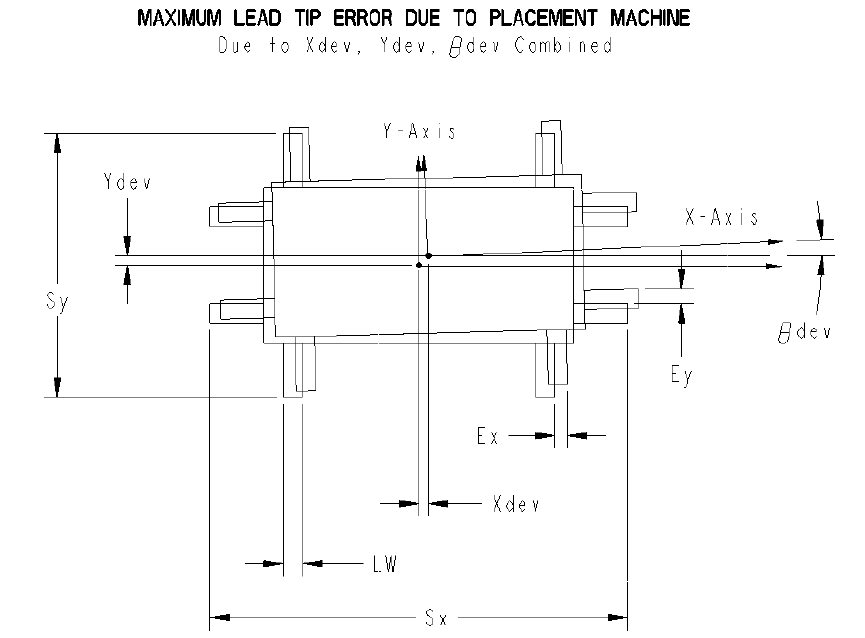
For leaded components, total error is referred to as maximum lead tip error (MLTE) . The word maximum is a part
of the metric name because the metric refers to the tip error experienced by the lead most impacted by the particular
combination of the X, Y, and θ deviations as shown in Figure 3-3. By definition, S
x
refers to the component span
(lead tip to lead tip) in one direction (X) while S
y
refers to the component’s span in an orthogonal direction (Y). For
area array components, total error is referred to as maximum ball error (MBE). Total error is then used to calculate
termination-to-land. Termination-to-land evaluation for the 1608 component is not performed, since the end-cap to
land proportions do not necessarily provide meaningful results. In this standard, the widely embraced IPC/EIA J-
STD-001 and IPC-A-610 standards are utilized.
Figure 3-3
Total error (for leaded and area array components) is then used to calculate termination-to-land, based on the
nominal component dimensions and the minimum land dimensions (IPC-SM-782). For leaded devices, termination-
to-land is based on the width of the lead. For area array components, termination-to-land is based on the percentage
of the land’s area that is in contact with the ball or column based on a two-dimensional mathematical model (not the
percentage of the ball that is on land since the land typically is designed to have a smaller surface than the ball). The
mean and standard deviation of these values for a group of placements are computed. The mean and standard
deviation are used to attain the Cpk’s values.
For this standard, Cpk for termination-to-land coverage is the parameter that quantifies the placement machine’s
capability of placing the component terminations on the associated lands. That is lead-to-land (LTL), ball-to-land
(BTL), depending upon the component type, in terms of the amount of termination that ends up on the land as a
result of the machine’s placement.

IPC-9850
Official Proposal
May 2001
16
Land sizes are defined by IPC-SM-782. Termination sizes used here are the nominal values (average of the
minimum and maximum values) (see Table 3-1). The Cpk is calculated relative to the 50% and 75% coverage called
for in the assembly standards.
Table 3-1 NEEDS TITLE
Component
Type
Component
Length x
Width
Termination
Width
Land
Length x
Width
Spec Limits for
Total Error
(Class 1,2)
Spec Limits for
Total Error
(Class 3)
SOIC-16 8.89 x 6.0 0.42 NA x 0.60 0.300
1
0.195
1
QFP-100 16.0 x 16.0 0.20 NA x 0.30 0.150
2
0.100
2
QFP-208 32.0 x 32.0 0.20 NA x 0.30 0.150
2
0.100
2
BGA-228 15.0 x 15.0 0.50 (Dia.) 0.45 (Dia.) 0.207
3
0.114
3
Notes
1. Requiring Total Error (for leaded this is MLTE) to be ≤ 0.195 for this SOIC is equivalent to requiring Lead-to-
Land to be ≥ 75%. The Total Error limit of 0.3 corresponds to LTL ≥ 50%.
2. Requiring Total Error (for leaded this is MLTE) to be ≤ 0.100 for this QFP is equivalent to requiring Lead-to-
Land to be ≥ 75%. The Total Error limit of 0.15 corresponds to LTL ≥ 50%.
3. Requiring Total Error (for area array this is MBE) to be ≤ 0.114 is equivalent to requiring Lead-to-Land to be ≥
75%. The Total Error limit of 0.207 corresponds to LTL ≥ 50%.
Calculation Method Calculation methods are provided for three component types: two leaded, one area array.
Termination-to-land calculations are based on IPC-SM-782 designed termination and designed land dimensions,
rather than actual ones. At time of publication of this standard, there is no standard for ball to land ratios for area
array components. A 0.5 mm diameter ball with a 0.45 mm land for the BGA228 was selected for calculation of this
metric.
Lead-to-land (LTL): is based on the percentage of the lead’s width that is placed on land. This measurement
quantifies the error for a component’s lead that experiences the most offset (of all the leads) due to the joint x, y, and
θ errors.
Calculation for a component with leads on four sides is shown here:
LTL=
⋅−
−
−
%100100
2
LeadWidth
LeadWidthLandWidth
MLTE
, where MLTE is defined below:
For a rectangular or square component with leads on four sides:
Maximum Lead Tip Error (MLTE) =
⋅+
⋅+
)sin(
2
)sin(
2
max
dev
S
xdev
dev
S
ydev
y
x
θ
θ
For a rectangular or square component with leads on its two longest sides:
If the component is placed so that the long sides are along the board’s X-axis,
Maximum Lead Tip Error (MLTE) = )evsin(
2
),max(
d
SS
xdev
yx
θ
⋅+