M7_ServiceManual_e.pdf - 第15页
1 Installation 1-7 ③ When the mounter is instal led stand alone, turn the adjust feet so t hat the PCB transfer height is t he same as the conveyor hei ght (900 ± 20mm (see Note)) of the reference equipm ent. In the case…
1 Installation
1-6
ACTION:
① Locate the mounter to the specified place.
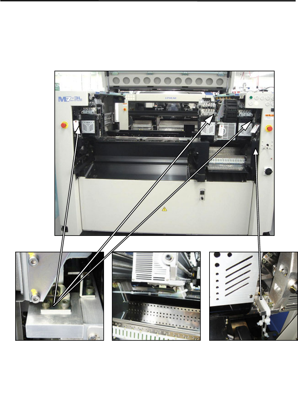
② Remove the followings: the bolt, metal fittings, and the nylon ties that fasten Beams that prevent to
move during transportation. Check to see that the X beams and heads can move to the Y direction
manually.
NOTE: Keep the removed metal fittings in case of moving the mounter for future reinstallation.
Nylon ties (Rear side)
Rear of the center beam
Metal fitting
on each head
Nylon tie (Front side)
Both at the left and right sides
The warning tag with “Remove
this.”
Only the center beam of M7-3S/3L is
fixed at the rear side
1 Installation
1-7
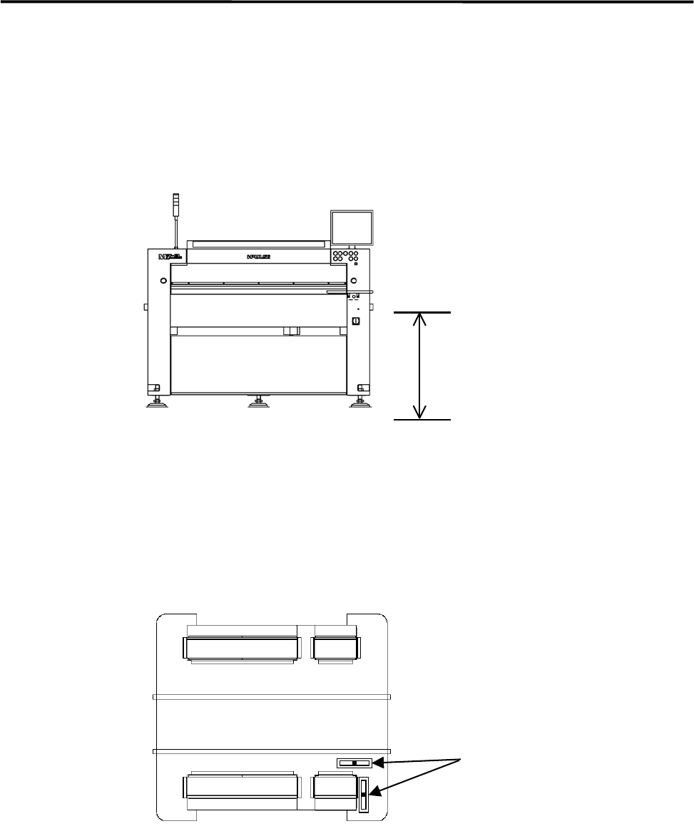
③ When the mounter is installed stand alone, turn the adjust feet so that the PCB transfer height is the
same as the conveyor height (900±20mm (see Note)) of the reference equipment. In the case of
SMEMA interface spec, the height must be 950±20mm.
④ When the mounter is connected to the Pre-process on production line, adjust the PCB transfer height
to the conveyor rail height of the Pre-process.
)
Production Line
NOTE: The height must be 890 to 920mm in the case of CFB wagon spec.
NOTE: The adjust feet must be turned using a M30 single-head wrench (nominal: 46mm).
⑤ Place a level on the base of the mounter. Set the position to the conveyor of the Pre-process finely until
the mounter is leveled.
) Supplementary Explanation for Installation
900±20mm
Or
950±20mm (SMEMA)
Level
1 Installation
1-8
⑥ After the mounter is positioned, make sure that a board runs smoothly between upstream and
downstream conveyors.
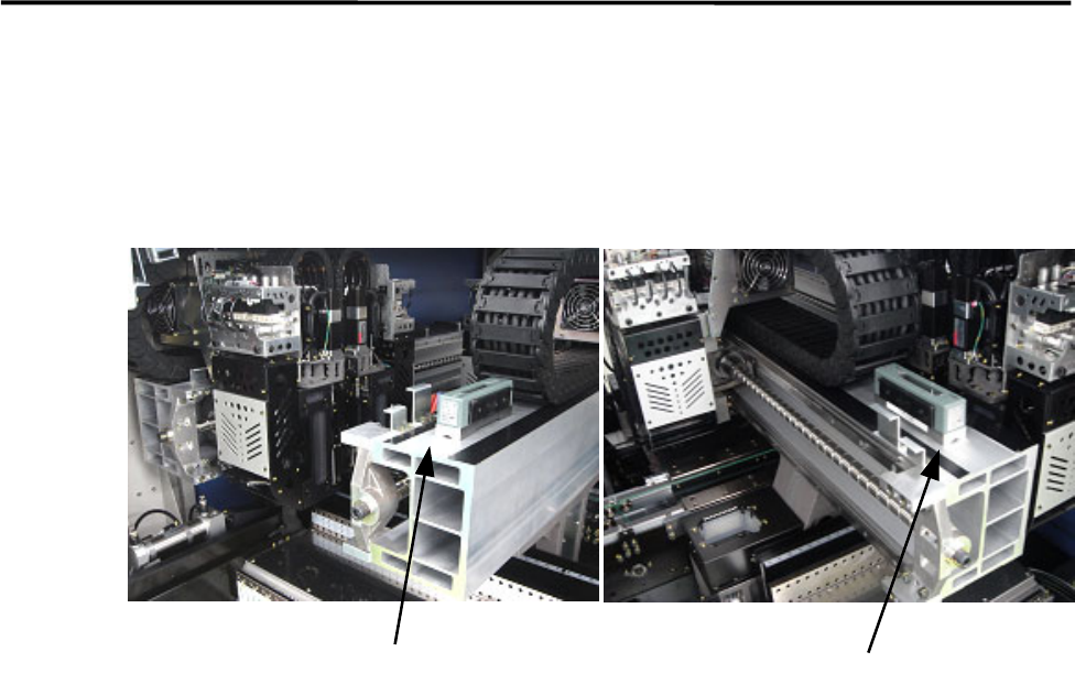
⑦ To prevent Y beam distortion, place a level on the Y beam and check the level when the Y beam is at
the rightmost end and the leftmost end. Adjust the level so the difference in level must be within 1 scale
(1 scale is 0.02mm/m).
⑧ Tighten the adjust-foot nuts.
NOTE: To tighten the adjust-foot nuts, use a closed wrench (nominal: 46mm) or a single-head wrench.
⑨ Connect the power cable to the power source independently. Do not use the same power source with
other machines that may be a noise source, such as a compressor and a welding machine.
⑩ Connect the mounter to ground.
⑪ Connect an intake-side air coupler 65SN or 85SN (Nitto Kohki) or equivalent to the air regulator
coupler located inside the mounter. When the coupler is connected, make sure the air regulator
indicates 0.50Mpa for the vacuum pressure and 0.40MPa for the vacuum break pressure.
Level
Level