M7_ServiceManual_e.pdf - 第63页
3 Mechanical Section 3-29 Specified Lubricants ■ M7 PART PART NO. GREASE NAME MANUFACTURER X/Y Axis Ball screw K48-M3856-000 GREASE NSK LG0-M86A3-00 GREASE,AFA THK X/Y Axis Linear guide LG0-M86A4-00 GREASE,AFB THK Silico…
3 Mechanical Section
3-28
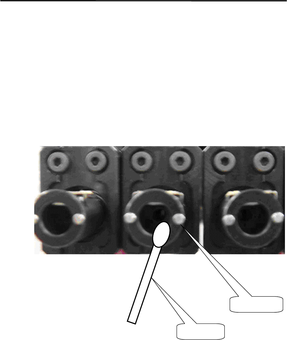
■ Application of grease on a Nozzle Holder
ACTION:
① Rub the inside of the Nozzle Holder with materials like a dry cotton swab to clean out the grime, such
as old grease.
② Use the head vacuum breaker to blow out the dust, such as fibers from a cotton swab.
NOTE: The head vacuum breaker can be executed by clicking the button at required head on the window of Main
Menu > Manual Menu > Actuator > On/Off > Head Vacuum.
③ Apply silicon grease evenly on the new cotton swab and rub the inside of the Nozzle Holder softly and
evenly with it.
④ After grease is applied, insert a nozzle and confirm that the nozzle escaping works smoothly.
Cotton Swab
Nozzle holder
3 Mechanical Section
3-29
Specified Lubricants
■ M7
PART PART NO. GREASE NAME MANUFACTURER
X/Y Axis
Ball screw
K48-M3856-000 GREASE NSK
LG0-M86A3-00 GREASE,AFA THK
X/Y Axis
Linear guide
LG0-M86A4-00 GREASE,AFB THK
Silicone Grease for
Nozzle
LG0-M89AB-00X GREASE,SILICON Three Bond (#1855)
■Grease Gun
Part Name
Part No. Remark
GUN,GREASE W/NOZZLE LG0-M86A1-00 Attached Grease gun and nozzle
NOZZLE* LC8-M86A1-00 Recommended nozzle for XY ball screws
*Higher strength Grease nozzle LC8-M86A1-00 is recommended to lubricate X/Y Ball screw.
NOTE: AFA grease is superior to AFB grease and can be used for all the axes.
NOTE: Order placement for lubricants can be accepted only if the mounter is delivered inside Japan. For locations
overseas, please consultant the agency where you purchased the mounter.
NOTE: Please specify Part No.
to place an order.
3 Mechanical Section
3-30
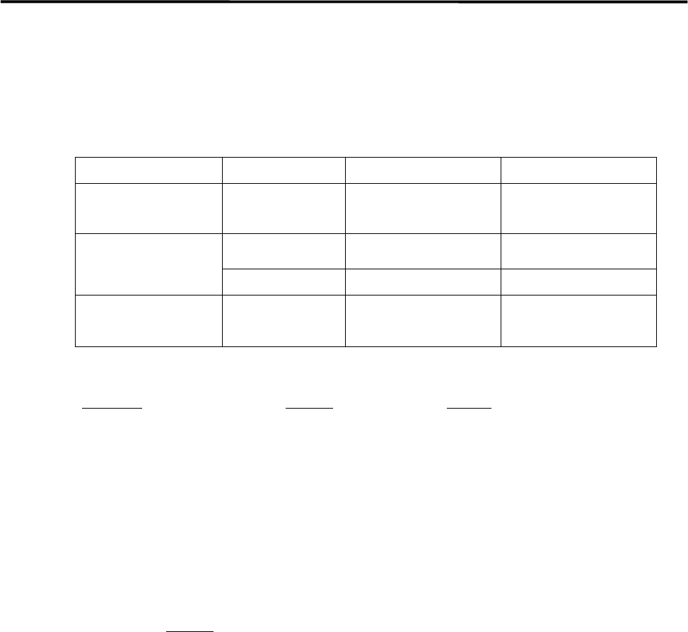
PCB Clamp Bar
There are the PCB clamp bars under the conveyor rail both the fixed and the movable sides.
The motion of the PCB clamp bar should be smooth not to allow PCB transfer problem to occur.
NOTE: Whenever you change the conveyor width, it is recommended to check the motion of the PCB clamp bars.
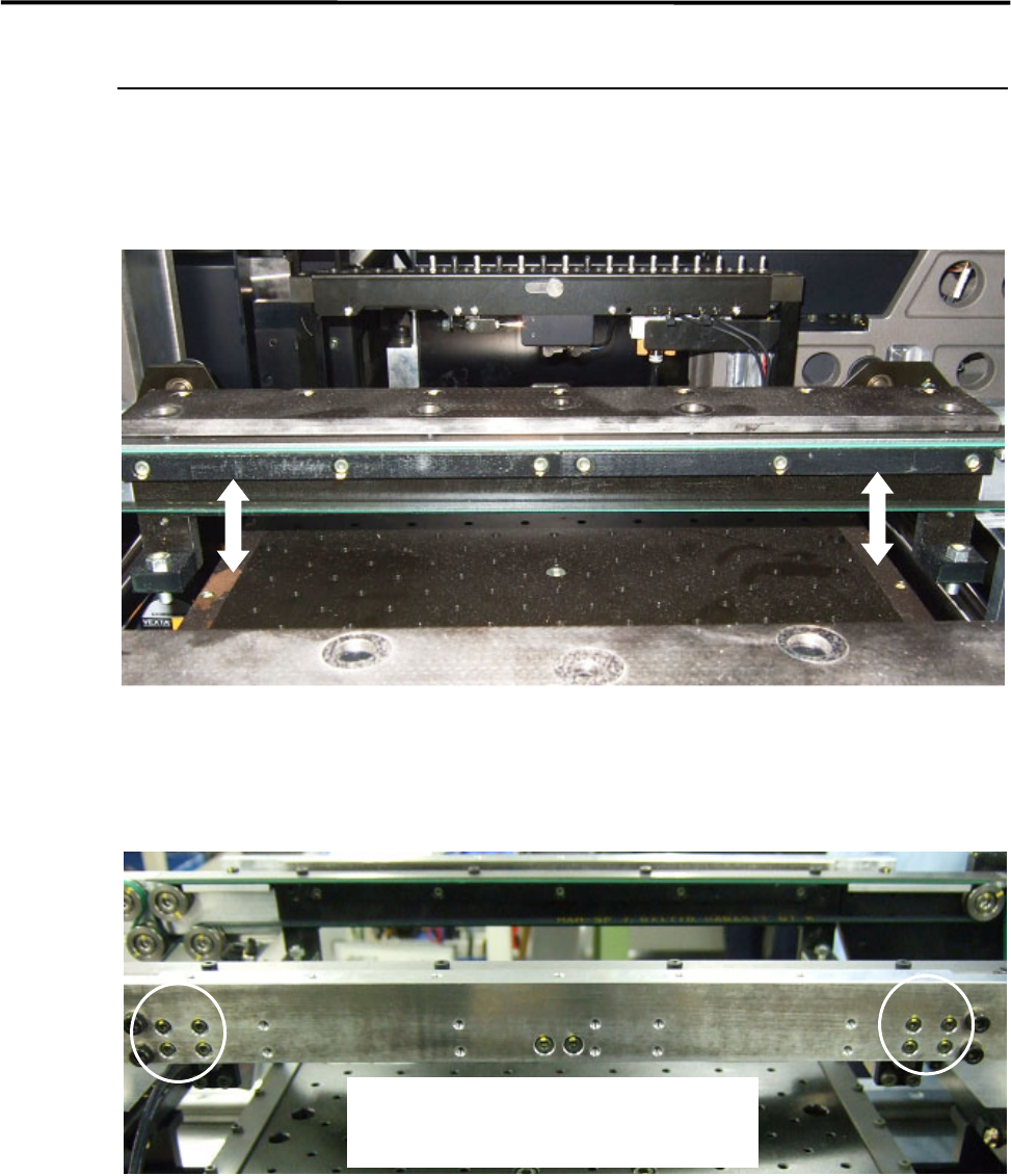
■ Adjustment
If the motion of the PCB clamp bar is not smooth, adjust the movable side of the PCB clamp bar only. The
fixed side is firmly tightened.
① Loosen the four screws on the PCB clamp bar at the PCB entrance side where the PCB stopper is
installed.
② To align the screw positions, keep pushing up the PCB clamp bar while tightening the four screws.
③ Move the PCB clamp bar up and down to make sure the motion.
NOTE: If the motion of the PCB clamp bar is not smooth and the mounter is operated, it may cause PCB transfer
problem.
To adjust the position of the PCB clamp bar,
loosen the four screws at the PCB entrance side.