M7_ServiceManual_e.pdf - 第17页
1 Installation 1-9 Intake-side air coupler 65SN/85SN (Nitto Kohki) or equivalent Mist Separator Air coupler Air Regulator (Vacuum, Others) 0.50MPa Air Regulator (Vacuum Break) 0.40MPa
1 Installation
1-8
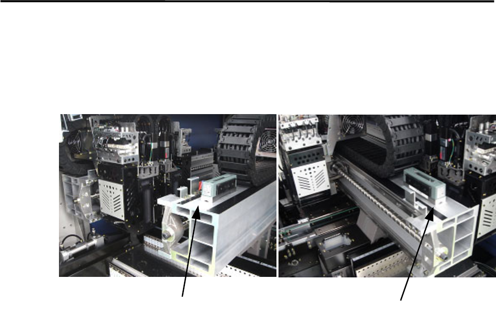
⑥ After the mounter is positioned, make sure that a board runs smoothly between upstream and
downstream conveyors.
⑦ To prevent Y beam distortion, place a level on the Y beam and check the level when the Y beam is at
the rightmost end and the leftmost end. Adjust the level so the difference in level must be within 1 scale
(1 scale is 0.02mm/m).
⑧ Tighten the adjust-foot nuts.
NOTE: To tighten the adjust-foot nuts, use a closed wrench (nominal: 46mm) or a single-head wrench.
⑨ Connect the power cable to the power source independently. Do not use the same power source with
other machines that may be a noise source, such as a compressor and a welding machine.
⑩ Connect the mounter to ground.
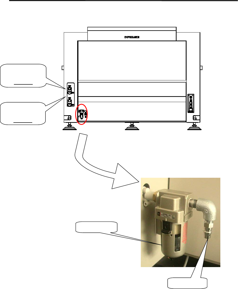
⑪ Connect an intake-side air coupler 65SN or 85SN (Nitto Kohki) or equivalent to the air regulator
coupler located inside the mounter. When the coupler is connected, make sure the air regulator
indicates 0.50Mpa for the vacuum pressure and 0.40MPa for the vacuum break pressure.
Level
Level
1 Installation
1-9
Intake-side air coupler
65SN/85SN (Nitto Kohki) or equivalent
Mist Separator
Air coupler
Air Regulator
(Vacuum, Others)
0.50MPa
Air Regulator
(Vacuum Break)
0.40MPa
1 Installation
1-10
Supplementary Explanation for Installation
When setting up a production line, level adjustment and line positioning of the mounter may be carried out
at the same time. However, to fine-adjust the mounter position with the mounter level, i-PULSE
recommends that the mounter be roughly positioned to the production line first, and then be leveled and
positioned accurately using the following four sets comprising a hydraulic jack and plates.
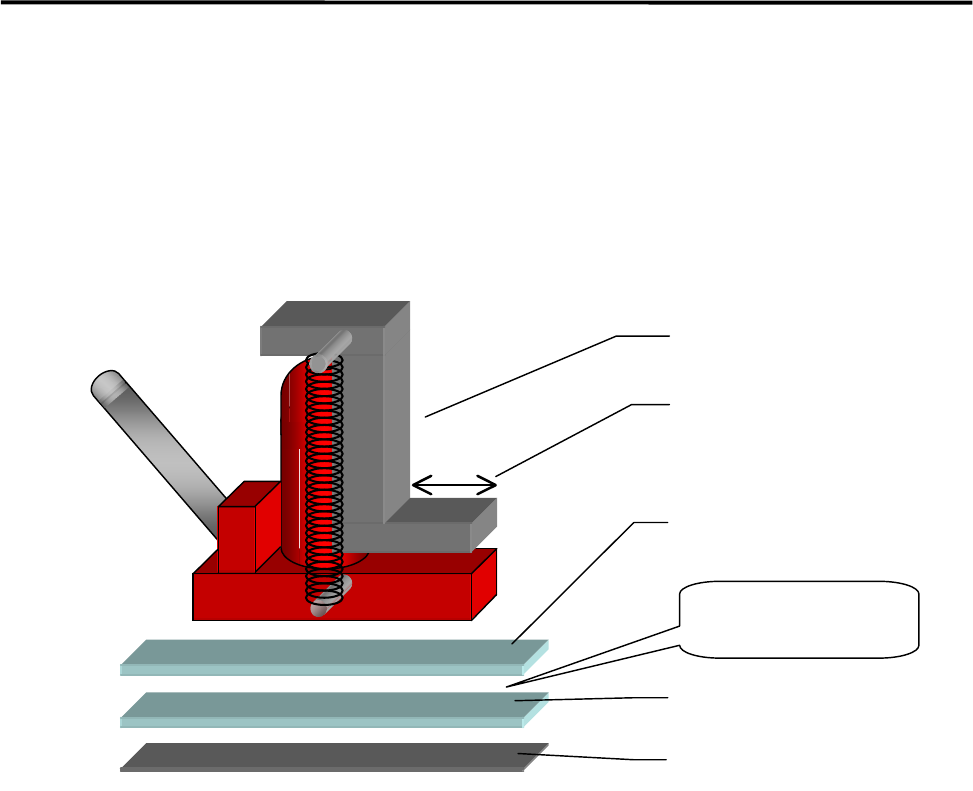
ACTION:
① Bond the non-slip base rubber with base plate 2.
② Apply grease between base plates 1 and 2 for lubrication purposes.
③ Place a plate set near each mounter jack-up point (four points).
④ Place a jack on each plate set and jack up the mounter.
⑤ Adjust each jack so that the mounter is level.
⑥ Fine-adjust the position of the mounter while the mounter is jacked up. (The mounter can be moved
lengthwise and crosswise with help of grease applied between the plates.)
Hydraulic jack
Base plate 1
Base plate 2
Base rubber
Apply grease
between the
p
lates.
Hook stroke