M7_ServiceManual_e.pdf - 第72页
4 Electrical Section 4-8 Serial I/O ■ Serial I/O List Device No. DO/DI M7-3L M7-2L M7-3S Communication Device1 DO control Device2 DI monitor Head A Head A Head A HIO_A Device3 DO control Device4 DI monitor Head B Head B …
4 Electrical Section
4-7
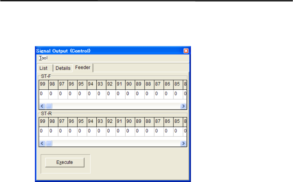
■ Feeder tab
This tab allows you to operate the tape feeders set in the front and rear feeder banks.
Action:
① Scroll left or right to display the desired feeder number.
② Click “0” of the desired feeder number “0” switches to “1”.
③ Click <Execute> button allows the feeder for one feeder indexing.
4 Electrical Section
4-8
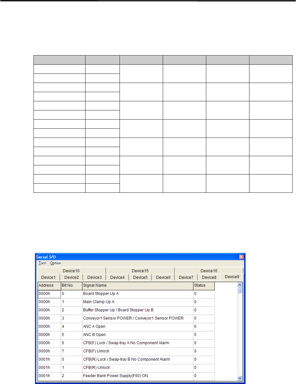
Serial I/O
■ Serial I/O List
Device No. DO/DI M7-3L M7-2L M7-3S Communication
Device1 DO control
Device2 DI monitor
Head A Head A Head A HIO_A
Device3 DO control
Device4 DI monitor
Head B Head B Head B HIO_B
Device5 DO control
Device6 DI monitor
Front Operation Front Operation Front Operation SWG6 (F)
Device7 DO control
Device8 DI monitor
Rear Operation Rear Operation SWG6 (R)
Device9 DO control
Device10 DI monitor
Conveyor Conveyor Conveyor CIO
Device11 DO control
Device12 DI monitor
MXR
Device15 DO control
Device16 DI monitor
Head C Head C HIO_C
Action:
① Click the cell corresponding to the desired actuator.
② At the same time you click the cell, the display changes 1(On) or 0(Off), and the actuator moves
accordingly.
Example:
■ Moving Up and Down the Board Stopper
① Select Manual> Signal I/O to open [Serial I/O] window.
② Select [Device9] tab.
③ Click [State] of [Board Stopper Up A] cell, Status changes “0” to “1” and the board stopper lifts. At this
time, confirm that State of [Board Stopper Up A (0002h)] in [Device10] switches from “0” to “1”.
To move down the board stopper, click [State] of [Board Stopper Up A] in [Device9]. And State changes
“1” to “0”. At this time, State of [Board Stopper Up A (0002h)] in [Device10] switches from “1” to “0”.
4 Electrical Section
4-9
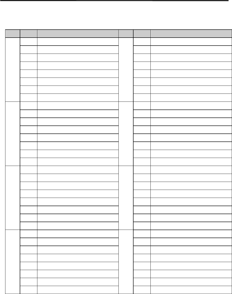
Signal Output Map
■ DO Control
Address Bit No. Signal Name Address Bit No. Signal Name
4181h 0 4185h 0 Fixed Camera Illumi. Address Bit0
1 1 Fixed Camera Illumi. Address Bit1
2 2 Fixed Camera Illumi. Address Bit2
3 SERVO ON Permission 3 Fixed Camera Illumi. Address Bit3
4 WARNING SOUND 4 Fixed Camera Illumi. Address Bit4
5 HAZARD SOUND 5 Fixed Camera Illumi. Address Bit5
6 6
7 7
4182h 0 Trigger Output Kind Bit0 4186h 0 UPS Shutdown
1 Trigger Output Kind Bit1 1
2 Trigger1 Output Place Bit0 2
3 Trigger1 Output Place Bit1 3
4 Trigger2 Output Place Bit0 4
5 Trigger2 Output Place Bit1 5
6 Trigger Output to Coplanarity Bit0 6
7 Trigger Output to Coplanarity Bit1 7
4183h 0 Signal Tower 1 On 3187h 0 Reserve DO
1 Signal Tower 1 Flash 1 Reserve DO
2 Signal Tower 2 On 2 Reserve DO
3 Signal Tower 2 Flash 3 Reserve DO
4 Signal Tower 3 On 4 Reserve DO
5 Signal Tower 3 Flash 5 Reserve DO
6 Signal Tower 4 On 6 Reserve DO
7 Signal Tower 4 Flash 7 Reserve DO
4184h 0 Fixed Camera Illumi. Data Bit0 4188h 0 Feeder Bank Bass-Line Separation
1 Fixed Camera Illumi. Data Bit1 1
2 Fixed Camera Illumi. Data Bit2 2
3 Fixed Camera Illumi. Data Bit3 3
4 Fixed Camera Illumi. Data Bit4 4
5 Fixed Camera Illumi. Data Bit5 5
6 Fixed Camera Illumi. Data Bit6 6
7 Fixed Camera Illumi. Data Bit7 7