M7_ServiceManual_e.pdf - 第65页
4 Electrical Section 4-1 4 Electrical Section
3 Mechanical Section
3-30
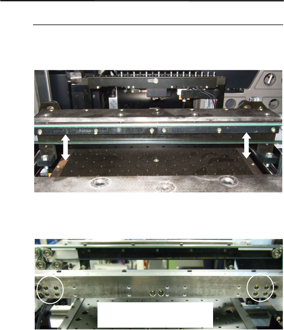
PCB Clamp Bar
There are the PCB clamp bars under the conveyor rail both the fixed and the movable sides.
The motion of the PCB clamp bar should be smooth not to allow PCB transfer problem to occur.
NOTE: Whenever you change the conveyor width, it is recommended to check the motion of the PCB clamp bars.
■ Adjustment
If the motion of the PCB clamp bar is not smooth, adjust the movable side of the PCB clamp bar only. The
fixed side is firmly tightened.
① Loosen the four screws on the PCB clamp bar at the PCB entrance side where the PCB stopper is
installed.
② To align the screw positions, keep pushing up the PCB clamp bar while tightening the four screws.
③ Move the PCB clamp bar up and down to make sure the motion.
NOTE: If the motion of the PCB clamp bar is not smooth and the mounter is operated, it may cause PCB transfer
problem.
To adjust the position of the PCB clamp bar,
loosen the four screws at the PCB entrance side.

4 Electrical Section
4-1
4
Electrical Section
4 Electrical Section
4-2
Signal I/O
Signal I/O is the abbreviation of signal input/output. The signal input refers to the input signal via the
sensors. The signal output refers to the command transmitted to the actuators.
Signal Output (Control) window serves as controls to move actuators for checking their movements. In
response to their movements, Signal Input (Monitor) window shows On/Off of motors and actuators.
Note: The Signal Input and Signal Out put windows are opened at the same time. You can move actuators using
the Signal Output window while simultaneously checking the signal input status in the Signal Input
window.
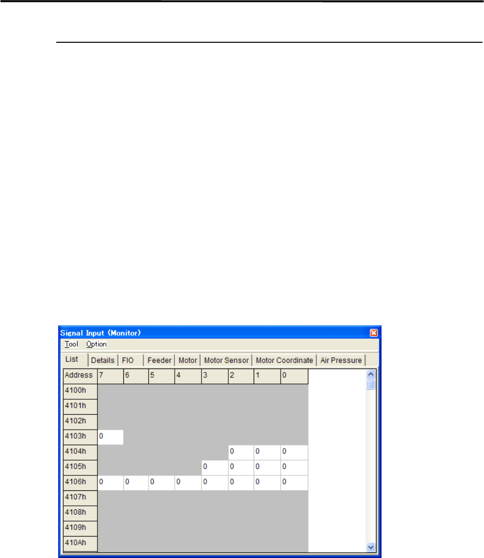
Signal Input Monitor
You can check On/Off of the sensors real-time. “1” indicates on, “0” off. When a sensor of a switch, motor,
and actuator responds, the change of the sensor status is shown real-time. Wire disconnection or sensor
failure can also be detected.
Menu: Manual>Signal I/O>Signal Input (Monitor)
These menus allow you to check each sensor status real-time. You can specify the sampling cycle for the
status check.
■ List tab
■ Changing the Sampling Cycle
Action:
① Select Option>SampingCycle.
② Enter sampling cycle (ms) larger than the minimum of 300, and click <OK> button.
③ Select Tool>StartScan to start checking.
④ Select Tool>EndScan to end.
Note: Use the minimum sampling cycle (300) normally.
Note: The combination of an address and bit number (0-7) represents a signal. The name of each signal is shown
in the Details tab.