IT Feeder Manual-45Series(English V2.0)Ver5.pdf - 第17页
IT Feeder System 1-5 1.3.2. Automatic Feeder Creation in PCB Edit If the IFS is used there is a <Create> button that creates the feeder in the “Feeder s” dialog box of the CP45F(V) MMI. When the ‘ Create ’ button i…
Samsung Intelligent Feeder System
1.3. MMI Add-On Functions in IT Feeder System
1.3.1. Toolbar
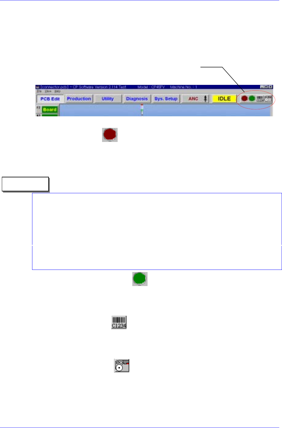
The CP45F(V) MMI S/W for IFS provides Toolbar buttons for IFS manipulation as
shown in [Figure 1-3] for the convenience of use. The functions of these buttons are as
follows.
FIS Toolbar Menu
Figure 1-3. Mark3 MMI Toolbar
Feeder Error Status
Displays the Feeder error status. The red icon flashes when there is a feeder error.
When the feeder error status is clicked regardless of the error status, the Feeder Error
Dialog box is displayed.
There are two types of Feeder errors; mismatch error and empty error. The error message
is displayed without differentiating which error it is. All errors are based on the PCB
program currently downloaded in the equipment.
Reference
The mismatch error is the case where there is a mismatch between the feeder type and
part name in the downloaded PCB program and the actual feeder type and part name
installed in the equipment.
‘Empty Error’ means that the feeder is not properly mounted in the machine although the
use of a feeder is registered in the PCB program. In such instance the machine does not
operate.
Part Shortage Warning Status
The green icon flashes when the part count of a feeder in use drops below the set part
count. Like the feeder error, when this status is clicked regardless of the current
warning status, the Part Shortage warning dialog box is displayed.
Manual Barcode Entry
If barcodes can not be read due to damaged barcodes or malfunction of the barcode
reader, click this button to display the manual barcode input dialog box. Click with
the mouse or use numeric keys to enter barcodes.
View FIS main window
Starts the FIS main window that shows feeder information in the PCB program and
actual feeder information.
1-4
IT Feeder System
1-5
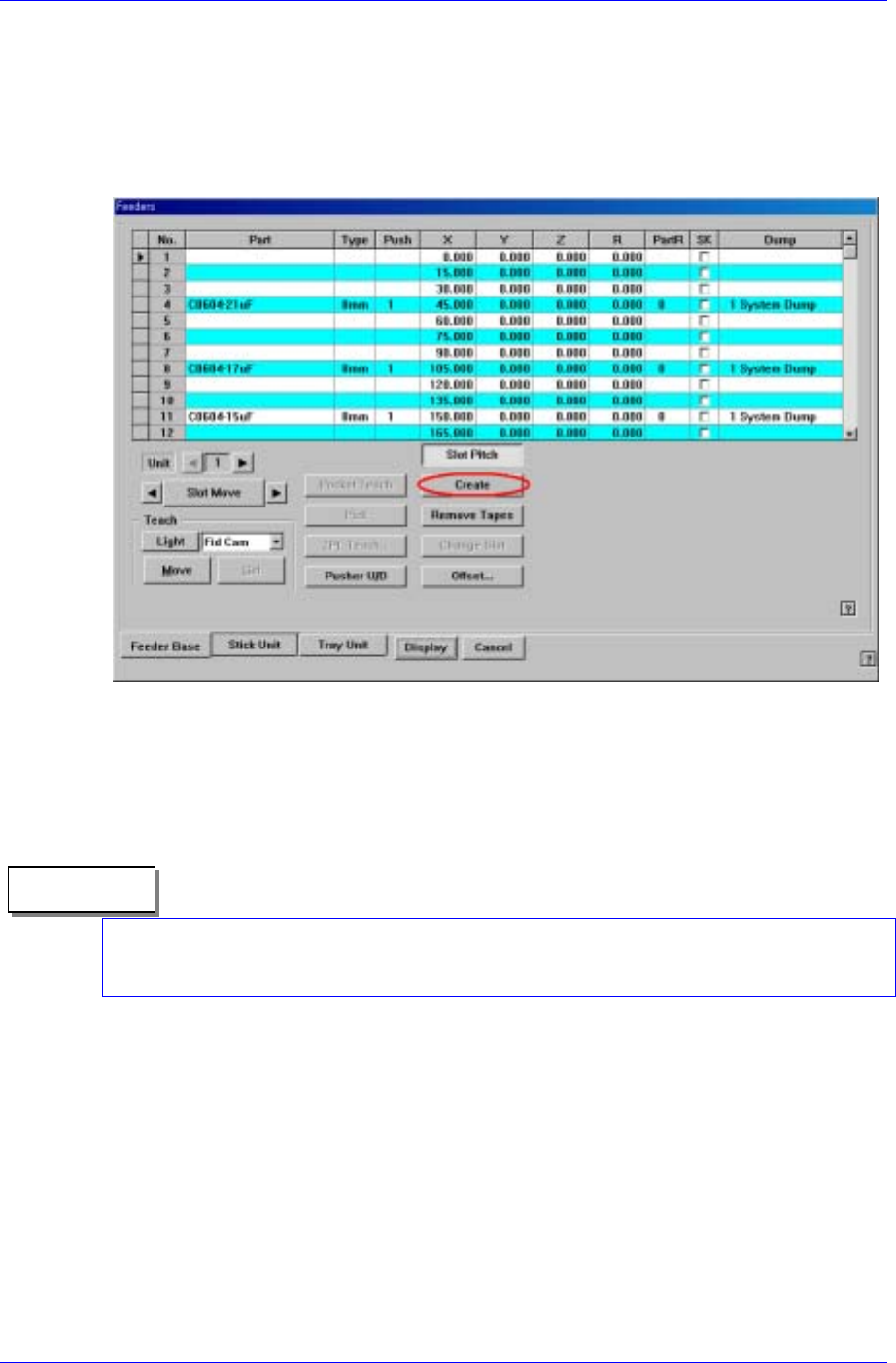
1.3.2. Automatic Feeder Creation in PCB Edit
If the IFS is used there is a <Create> button that creates the feeder in the “Feeders” dialog
box of the CP45F(V) MMI. When the ‘Create’ button is pressed, the information on the
feeder being installed on the feeder base is automatically registered in the ‘PCB’ file in
operation. In this case, the feeder information already registered in the ‘PCB” file is
deleted.
Figure 1-4. Feeder creation in PCB Edit
1.3.3. Part Library Synchronization with IFS Database
The parts registered in the equipment are automatically registered in the IFS database.
Therefore, take precautions for the parts that have identical names but have different data.
All equipment that uses IFS (CP40, CP45, …) and off-line systems (Feeder Station, Part
Station) share a common IFS database as well as part names. Therefore, to benefit from
using IFS, it is necessary to control part names systematically.
Reference
When a component is registered under a new name (New Part) or duplicated
(Duplicate) in the ‘Parts’ dialog box as in [Figure1-5], the newly created part is added in
the Part Library automatically. And the added part is automatically registered if it does
not exist in the IFS database already.
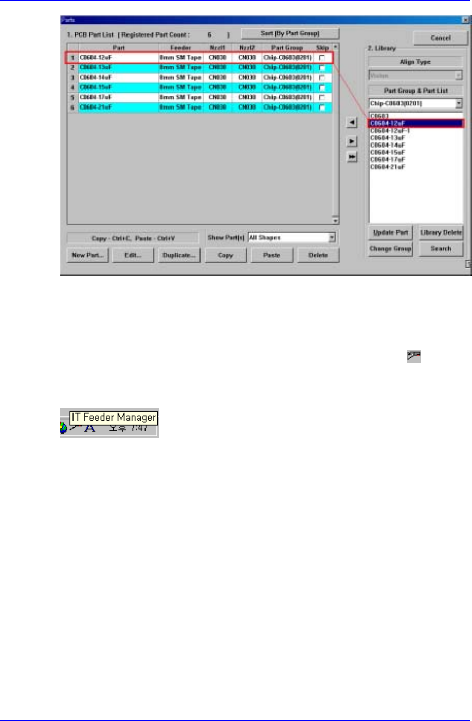
Samsung Intelligent Feeder System
Figure 1-5. Part library addition
1.4. Feeder Information Server (FIS)
When Mark3 MMI is started and FIS is executed normally, the FIS icon ( ) appears
in the System Tray of Windows as shown in [Figure 1-6]. When the mouse pointer is
located on this icon, a tool tip describing “Feeder Scanner Controller” is displayed as
shown in the figure.
Figure 1-6. Windows System Tray and FIS Icon
FIS consists of one main window and several status dialog boxs. All manipulation is
carried out by the MMI Toolbar buttons.
1.4.1. FIS main window
The FIS main window displays the PCB program currently loaded in the equipment, the
feeder array and component to be mounted in the feeder in the program, types of feeders
installed in the actual equipment and their part counts. The screen structure is shown in
[Figure 1-7].
The FIS main window is not displayed unless a certain manipulation is taken by the user.
Execute Display FIS Main Window to view the feeder in the PCB program downloaded
in the equipment, ID of the feeder mounted on the actual equipment, and other
information. There are two ways to view the FIS main window. Firstly, pressing the
right most button on the FIS Toolbar menu of Mark3 MMI Toolbar in [Figure 1-3]
displays the FIS main window.
Secondly, double click on the left button of the mouse on the FIS icon from System Tray
in [Figure 1-6].
1-6