IT Feeder Manual-45Series(English V2.0)Ver5.pdf - 第72页
在线预览 IT Feeder Manual-45Series(English V2.0)Ver5.pdf PDF 文档。
Feeder Station
please consult with Samsung Techwin.
It is programmed to support only the keyboard edge type supplied by us.
3.4.5. Connect Database [Ctrl+F5]
When the connection with the Oracle Database is disconnected, attempt connection once
again.
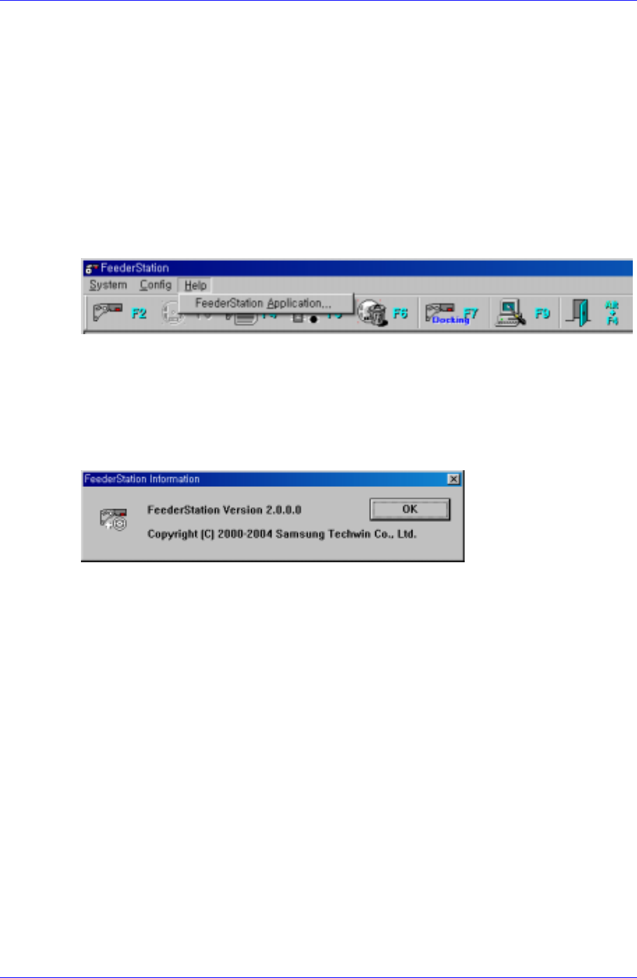
3.5. Help menu
When the Help menu is selected on the Main menu bar, the following submenu appears.
Figure 3-22. Submenu screen
3.5.1. Feeder Station Application…
When the Feeder Station Application… menu is selected, the following screen appears.
The screen displays the Feeder Station Version information and tells that Samsung
Techwin has the copyright.
Figure 3-23. Feeder Station Information screen
3-17

Specifications And Technical Drawing & PartList
Chapter 4. Specifications And Technical
Drawing & PartList
4.1. Applicable range
4.1.1. Component Placer
In the CP40 series and CP45F(V), it only applies to machines that have the IT Feeder
System Option.
4.1.2. Software
Used in the MMI Version 2.500/VME 3.530 and above.
IT Feeder System Version 2.000
Part Station Version 2.000
Feeder Station Version 2.000
4.1.3. Feeder
The Pneumatic IT Tape Feeder With RF-ID TAG can be mounted.
8,12,16,24,32,44,56mm Pneumatic IT Tape Feeder
12, 16, 24, 32, 44, 56mm Pneumatic IT NST Feeder
4.2. Configurations
4.2.1. Mechanical Part
Feeder Base: It is where the Feeder is mounted.
RF-ID Driving: It move the ID Scan Device Using the Step Motor and Timing Belt.
Switch: It consist of Ball and Switch Pin. It let the Switch Board know if the IT
Feeder is mounted or not.
4.2.2. Control Part
Antena Board: It scan the RF-ID TAG attached to IT Feeder.
Reader Board: Transmits data between the Antena Board and the IT CPU Board
installed in the equipment.
Switch Board: Checks whether a feeder is installed in each slot of the Feeder Base.
Flat Cable: Cable for data transmission between the Antena Board and the Reader
Board.
Cart Ext Cable: Cable for data transmission between the IT Feeder Base and the IT
CPU Board installed in the equipment.
4-1