IT Feeder Manual-45Series(English V2.0)Ver5.pdf - 第61页
Feeder S tation when the Feeder Id and Reel Code are entered and saved in the DB normally . Uninstalled: The Uninstalled status wo rks only in the Uninstall Mode. It is displayed when the Reel is removed from the Feeder …
Samsung Intelligent Feeder System
3) The perviously inputted part reel information moves down to the lower side
of the screen and the screen changes to the state waiting for the second part
reel.
4) Read the barcode of the second part reel to be spliced.
5) The two different part reels are connected and displayed on the screen. The
user then physically connects the part reel.
How to detach:
1) If the part reel barcode is read, the part reel information is indicated on the
screen.
2) In the event of a spliced barcode, the Cancel button becomes enabled.
3) If the Cancel button is clicked, then the splicing is disconnected.
The splicing function is available only in the Find mode. The number of part reels that
can be spliced is two. When the reels are spliced, the button is disabled.
Reference
※ In order to install the part reel in the feeder, the 2
nd
part reel barcode must be read.
Install Mode: The mode to install the Part Reel in the Feeder. Installation is
possible only when an operation has been started. When the operation data is
entered after pressing the start button (Figure 3-8), the mode changes to the
Install Mode. To return to the Install Mode after a mode change during an
operation, press the Install button
to return to the Install Mode, then
install the Part Reel in the Feeder.
How to install:
1) First, read the feeder ID with the RF-ID Reader to indicate feeder
information in the screen.
2) Install the part reel in the feeder and read the barcode of the
corresponding part reel. In the case of an effective barcode, the
information is indicated in the screen and the connection rings are
created between the feeder and part reel.
3) Installation of the part reel in the feeder is completed.
Attempting to read a previously installed feeder will generate the
message that it has previously been installed.
Uninstall Mode: The mode to remove the Reel installed in the Feeder. Press
the button to use it. In the Uninstall Mode, reading a Feeder ID or
Reel Code deletes it immediately. Use caution when uninstalling the part reel.
Operation status display on the lower right (Figure 3-6)
Ready: When the Ready status turns green, it is ready for an operation. When
a Feeder ID or Reel Code is entered in the Find or Uninstall Mode, the result
is displayed immediately, but in the Install Mode, it shows the Feeder ID
input standby status.
Standby: The standby status works only in the Install Mode. When a Feeder
ID is entered, it turns green and becomes the Reel Code input standby status.
Installed: The installed status works only in the Install Mode. It is displayed
3-6
Feeder Station
when the Feeder Id and Reel Code are entered and saved in the DB normally.
Uninstalled: The Uninstalled status works only in the Uninstall Mode. It is
displayed when the Reel is removed from the Feeder and the data is saved in
the DB normally.
Error: The Error status is displayed when saving data to the DB in the Install
or Uninstall Mode is unsuccessful. (Figure 3-5)
Figure 3-5. Error status display
Figure 3-6. Operation status display
Additional work
Starting an operation
To install a Part Reel in the Feeder, the destination Feeder should be specified.
When the Start button in Figure 3-7 is pressed, Figure 3-8 is displayed. When the
Start button is pressed after setting the worker number, product name, line to
install, equipment to install, and front/back, it is ready for Feeder installation.
The information entered above is printed on a Work Sheet and sent to the line
along with the registered Feeder.
Figure 3-7. Start Operation button
Figure 3-8. Operation information input screen
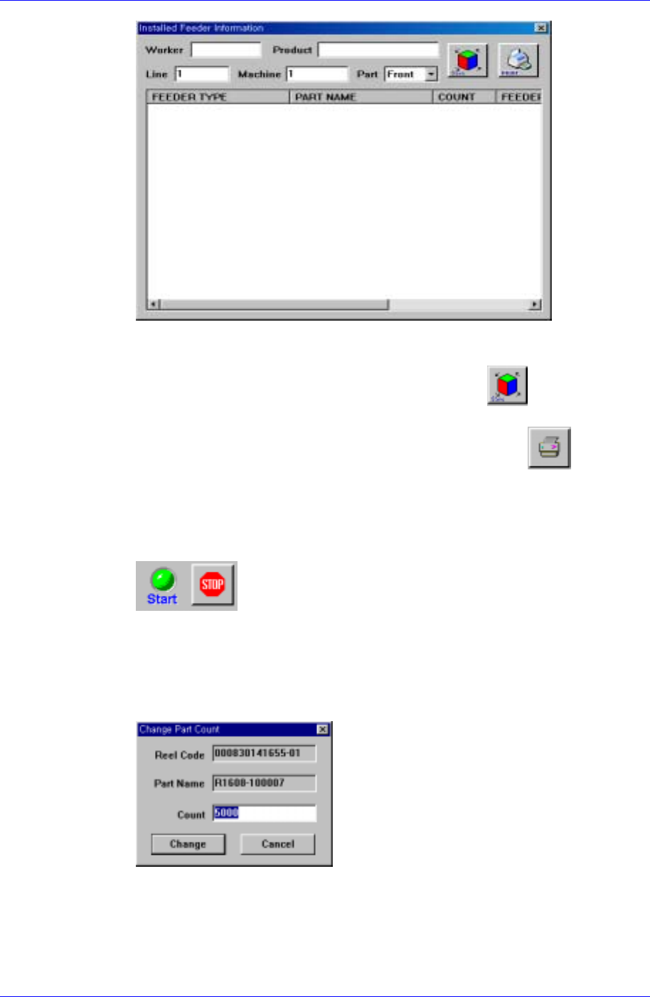
Searching an operation
Searches information on the Feeder in operation or completed Feeders. The result
can be made into a Work Sheet. When the
button is pressed, Figure 3-
78is displayed.
3-7
Samsung Intelligent Feeder System
Figure 3-9. Operation information screen
Figure 3-9 displays the registered Feeder information, worker, product name, line,
equipment and front/back information. Pressing
after modifying
information on worker, product name, line, equipment, or front/back changes the
information to the modified one. To print a Work Sheet, press
.
Ending an operation
Pressing the Stop button in Figure 3-10 after finishing Feeder installation ends
the operation. The Install Mode is disabled and only the Find and Uninstalled
modes are abled.
Figure 3-10. Operation stop button
Changing the component count
Possible to change the component count for the selected Part Reel. Pressing the
Change button displays Figure 3-11. Changing the component count and pressing
the Change button saves the changed number in the DB.
Figure 3-11. Component count change screen
Feeder registration
In case a new RF-ID Feeder is delivered, the feeder ID must be registered in the
database prior to use. In the Feeder Info[F2] screen if a non-registered feeder ID
is recognized, the Feeder Registration Dialog box is displayed. Enter the feeder
3-8