IT Feeder Manual-45Series(English V2.0)Ver5.pdf - 第24页
Samsung Intelligent Feeder System Figur e 1-14. FIS main wind ow view menu c onfiguration 1.4.4.1. Error When the PCB program is downloaded to the equi pment, FIS checks the error of the feeder installed on the feeder ba…
IT Feeder System
1-11
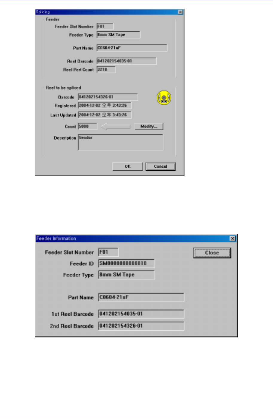
Figure 1-12. Screen configuration after splicing is completed
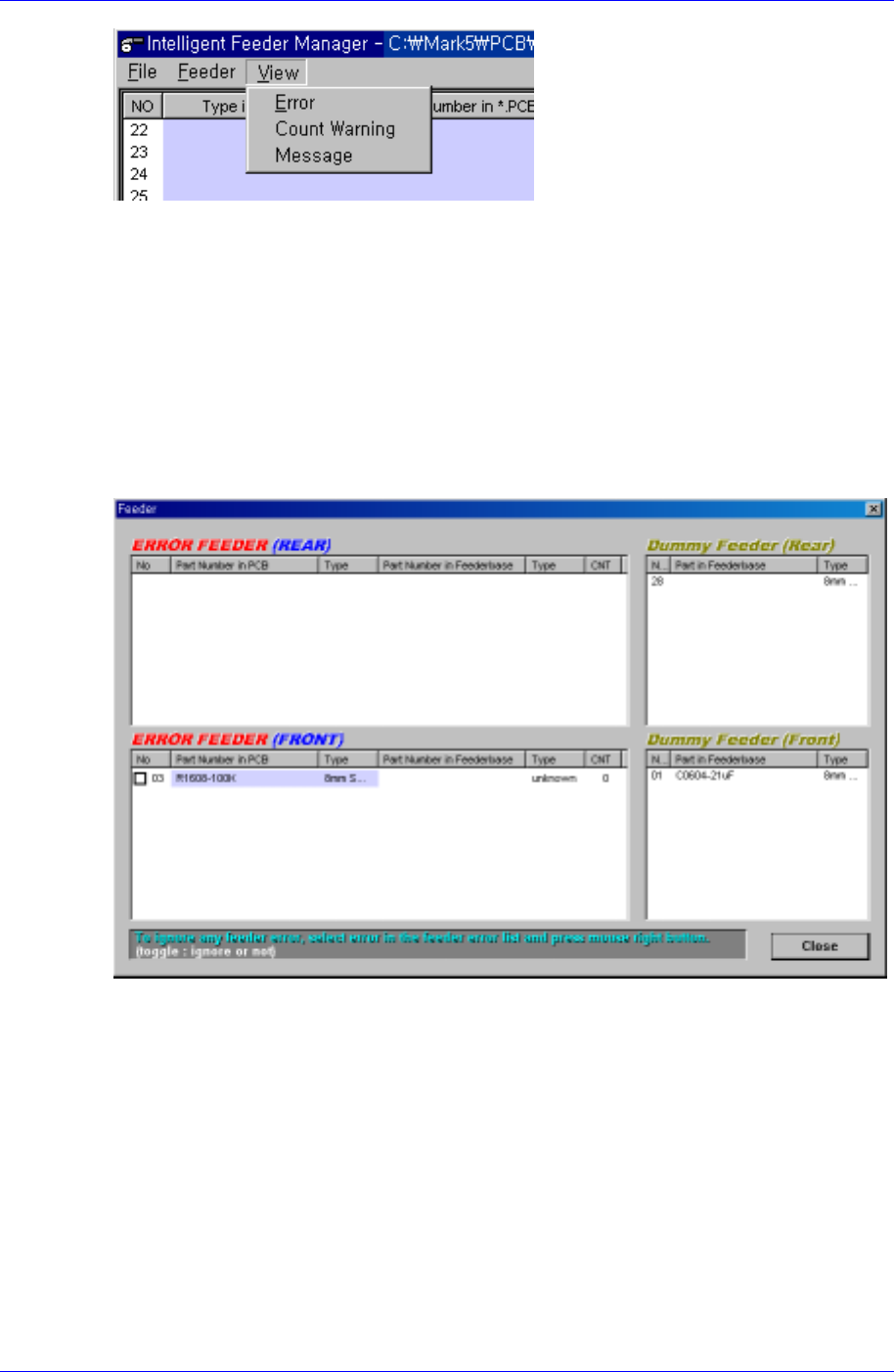
1.4.3.2. Feeder Info
The selected feeder information can be checked. After selecting the feeder to be checked,
select <Feeder Info> in <Feeder>. Then the feeder information can be checked as shown
in the following figure.
Figure 1-13. Feeder information screen configuration
1.4.4. Structure of the View Menu
This is the menu from which error status and remaining quantity warning message are
displayed. Figure. 1-14 shows the menu configuration.
Samsung Intelligent Feeder System
Figure 1-14. FIS main window view menu configuration
1.4.4.1. Error
When the PCB program is downloaded to the equipment, FIS checks the error of the
feeder installed on the feeder base. The feeder array, feeder type, and part name
programmed in the PCB program are compared with the feeder information of currently
installed feeder. If there are any discrepancies, an error message occurs and the operation
stops.
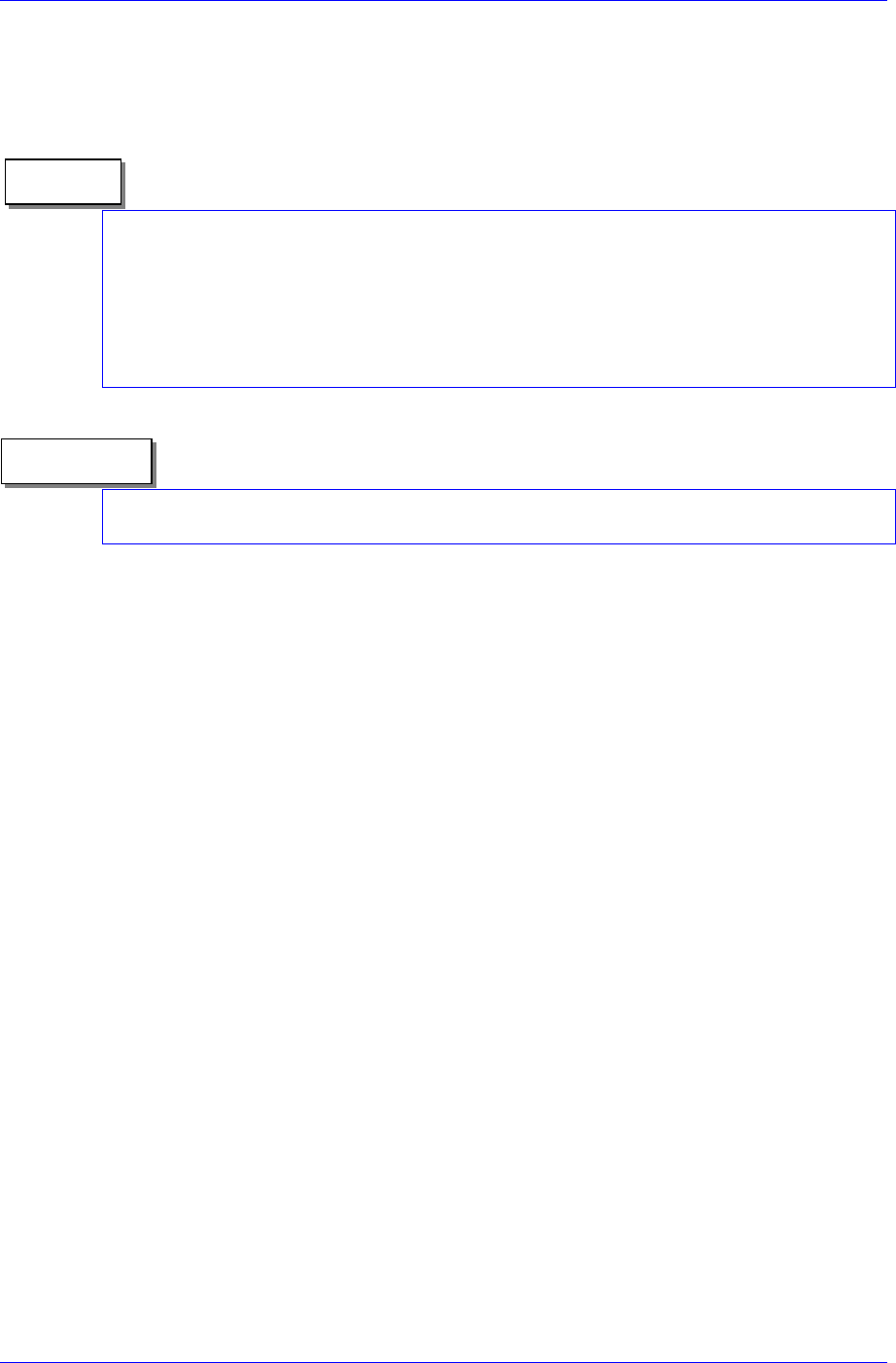
When a feeder error occurs, the dialog box in [Figure 1-15] is displayed automatically,
and the latest error in the list is selected.
Figure 1-15. Feeder error dialog box
The list is displayed separately for the front and rear and the items displayed in the dialog
box are as follows.
Error feeder list
Indicates the contents of the currently occurred error. The first column of the list is
the Feeder column, where the slot number of the feeder in which the error has
occurred is indicated. The next two columns indicate the feeders and parts in the PCB
program. The remaining 3 columns indicate the contents of the feeders actually
mounted. If the contents of the feeder are different from the feeders and parts in the
PCB program, an error occurs. If the <Part Number in Feeder Base> column is empty,
it signifies Empty error. If it is filled, it signifies Mismatch error.
When a Mismatch error occurs, it is immediately indicated through the lamp and
alarm. When an Empty error occurs, it is indicated only through the lamp.
1-12
IT Feeder System
1-13
Dummy (or extra) feeder list
If a feeder is installed on the feeder base but it is not programmed as a feeder in use
in the program, it is listed in the dummy list.
Disregarding the error: The equipment is not operated unless feeder errors are resolved.
If the equipment recognizes a feeder error due to damage to feeder ID or other reasons
even though it is not a real situation, the error can not be resolved automatically and the
equipment can not be operated. In this case, disregard the error, then the error check
does not appear for the respective feeder. Select the error feeder to disregard, click on the
right button of the mouse, then the box for feeder number column is checked and the error
is disregarded.
Memo
Even though the Feeder error dialog box is closed, the error status continues. To view the
error, click “Feeder error status” on the MMI Toolbar.
Reference
Feeder error restoration procedure
Empty Feeder
① If an Empty feeder exists, locate it in the error list.
② Find the feeder having the identical part name in the Dummy list.
③ If the feeder exists, move the feeder in the Dummy list to the corresponding
empty slot and mount the feeder.
④ Check that the empty error is cleared.
⑤ Check that the feeder in the Dummy list is removed.
⑥ Confirm that the feeder error does not occur.
Mismatch Feeder Error
① If a Mismatch error feeder exists, locate it in the error list.
② Move the Mismatch error feeder to the unused slot and keep it in the slot.
③ Confirm that the moved feeder is added to the Dummy list.
④ Check if any feeder whose type and part name are identical to the feeder in
the error occurred slot exists.
⑤ If it exists, move it to the empty error slot and mount it.
⑥ If it does not exist, mount a new feeder.
1.4.4.2. Count Warning
If a feeder is programmed as the feeder in use in the PCB program, FIS counts the
remaining components in the feeder. In this case, if FIS is set to generate a part shortage
warning when the part count drops below a specified number, the part shortage warning
dialog box is displayed on the screen automatically and the green icon flashes in [Figure
1-3].