Eaton 9155 8-15 kVA.pdf - 第16页
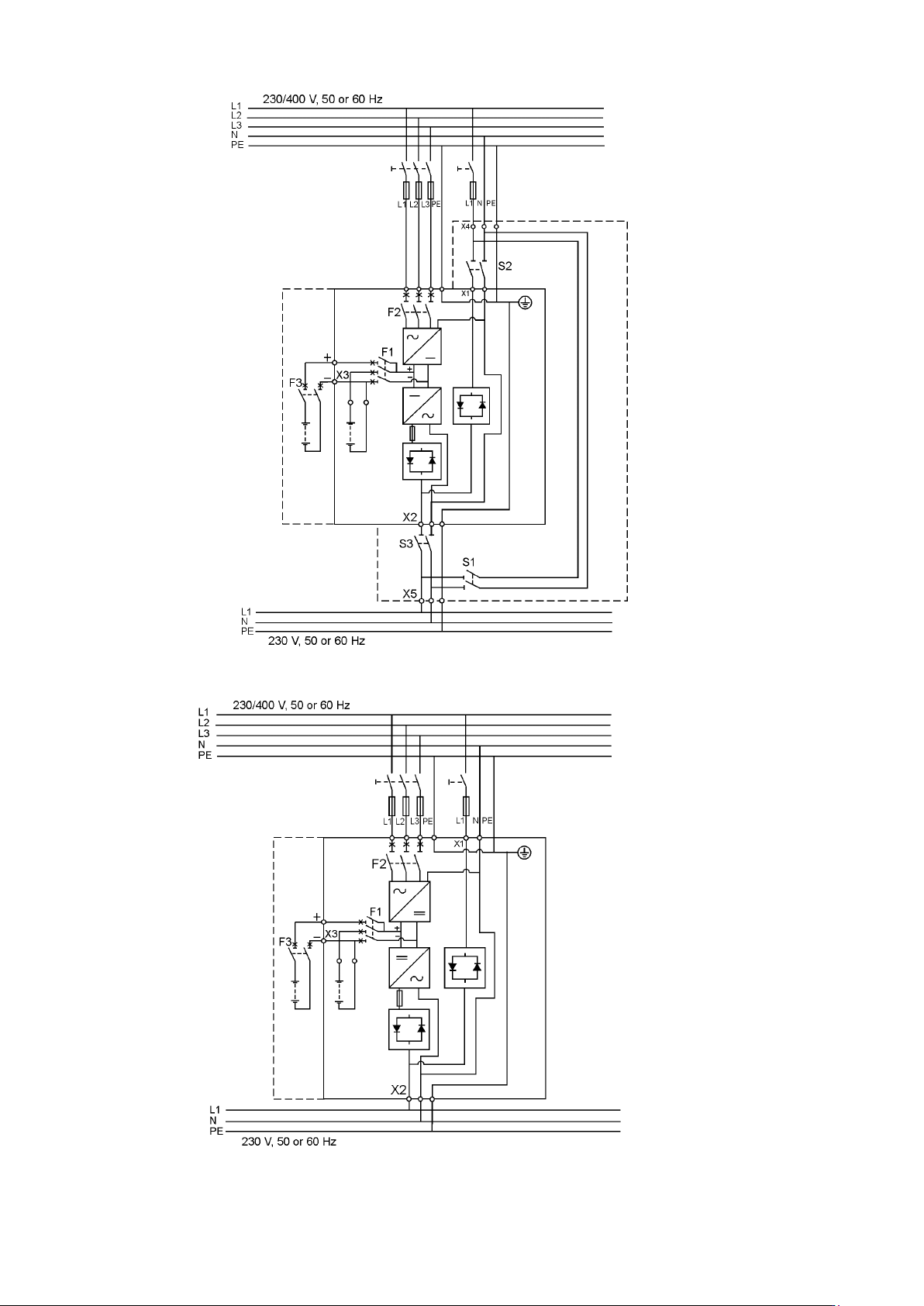
UPS 8 – 15 kV A, 230V 50/60 Hz output User ’ s Guide 1 022403 Revision D 16 Figure 15. Wiring diagram of UPS N-model (3-ph rectifier) with integral MBS. Figure 16. Wiring diagram of UPS N-model (3-ph rectifier).
UPS 8 – 15 kVA, 230V 50/60 Hz output
User’s Guide
1022403
Revision D
15
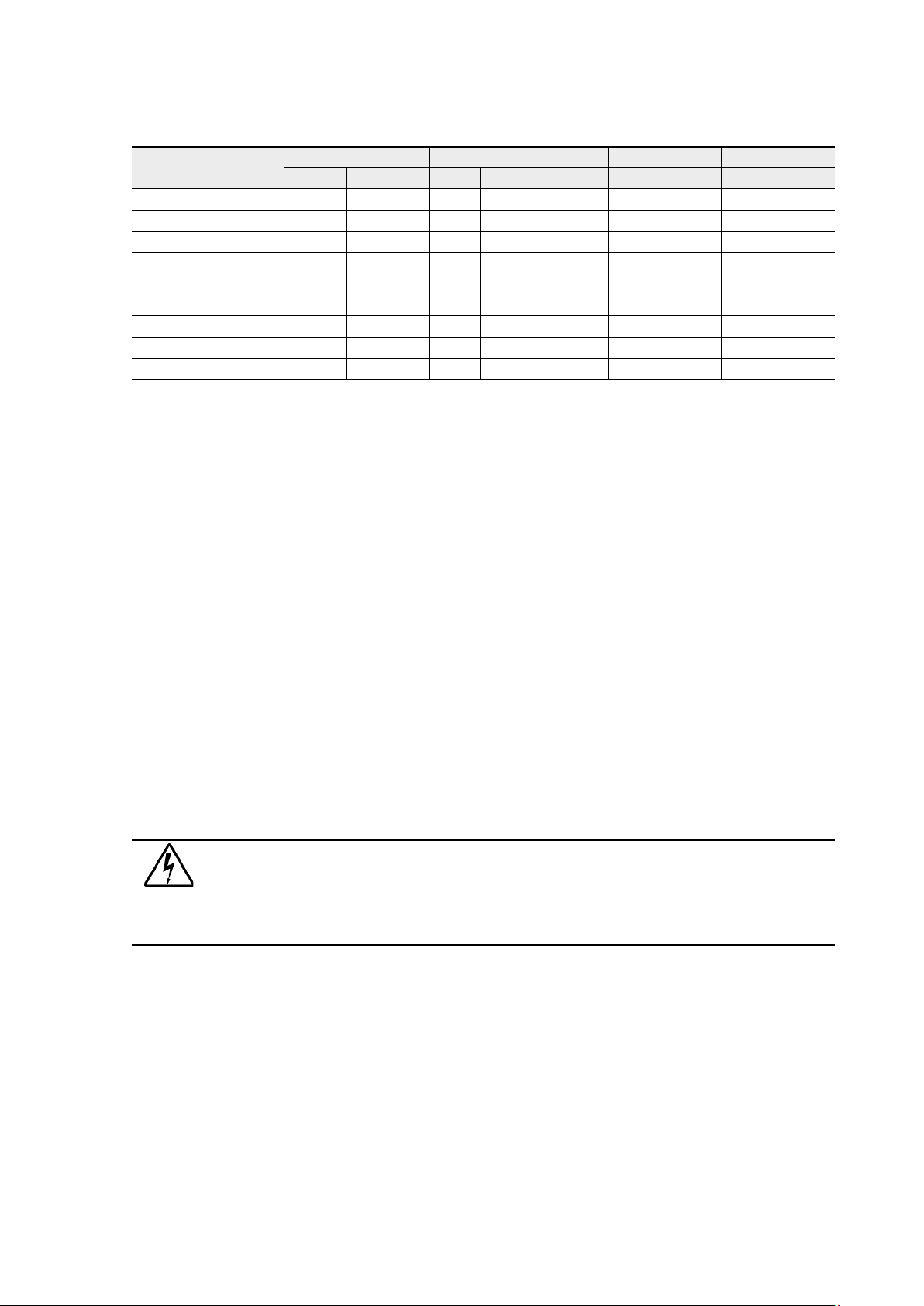
Contact the manufacturer’s authorised agent or the local office for assistance at fuse and cable
sizing. Refer to the recommended cable and fuse ratings in the below table.
Table 14. Cable and fuse ratings for the different UPS ratings
(*With optional limited charging feature at low input and high kW load, see User Settings)
Wiring procedure
The power cable terminals are located in the back of the UPS unit. The service personnel is
responsible for the correct electrical installation. They must be authorised by the manufacturer.
The installation procedure:
1. Remove the cover(s) of the terminal box of the power cables with a screwdriver.
Refer to the dimensional drawing for the correct location at the back of the unit.
2. Slide the cables through the grommets of the connection box.
3. Connect the conductors of the rectifier and bypass input cables to the proper terminals.
With single phase unit it is recommended to use the same phases for rectifier and bypass
inputs.
4. Connect the conductors of the load cable to the proper terminals.
5. Connect the conductors of an external battery cabinet cable to the external battery +,
- and PE terminals. Check for the correct polarity.
See External Battery Cabinet (EBC) installation procedure.
Warning!
If available, the internal battery has to be disconnected first because the external
battery terminals are hazardous due to the parallel battery string.
6. Secure the cables with the grommets in the connection box.
7. Fasten the cover of the terminal box with a screwdriver.
The IEC/EN 62040-1 safety instructions require the fitting by the user of a warning label on all
primary power isolators installed remote from the UPS area. The warning label for electrical
maintenance personnel shall carry the following wording or equivalent:
“ISOLATE UNINTERRUBTIBLE POWER SUPPLY (UPS) BEFORE WORKING ON THIS CIRCUIT.”
A readily accessible disconnect device shall be incorporated in the building installation wiring
as shown in diagrams.
UPS rating
Input Bypass Load PE Battery
Fusing Cable Fusing Cable Cable I nom Cable Cable Fusing
8 kVA 3-phase 3x16 A 3x2.5 mm² 50 A 10 mm² 10 mm² 34.8 A 10 mm² 10 mm² 50 A
1-phase 50 A 10 mm² 50 A 10 mm² 10 mm² 34.8 A 10 mm² 10 mm² 50 A
10 kVA 3-phase 3x16 A* 3x2.5 mm² 50 A 10 mm² 10 mm² 43.5 A 10 mm² 10 mm² 50 A
3-phase 3x20 A 3x4 mm² 50 A 10 mm² 10 mm² 43.5 A 10 mm² 10 mm² 50 A
1-phase 63 A 16 mm² 50 A 10 mm² 10 mm² 43.5 A 10 mm² 10 mm² 50 A
12 kVA 3-phase 3x25 A 3x6 mm² 63 A 16 mm² 16 mm² 52.2 A 16 mm² 10 mm² 50 A
15 kVA 3-phase 3x25 A* 3x6 mm² 80 A 25 mm² 25 mm² 65.2 A 16 mm² 10 mm² 50 A
3-phase 3x32 A 3x10 mm² 80 A 25 mm² 25 mm² 65.2 A 16 mm² 10 mm²
Maximum 3-phase 3x63 A 3x16 mm² 80 A 35 mm² 35 mm² 35 mm² 16 mm²
UPS 8 – 15 kVA, 230V 50/60 Hz output
User’s Guide
1022403
Revision D
16
Figure 15. Wiring diagram of UPS N-model (3-ph rectifier) with integral MBS.
Figure 16. Wiring diagram of UPS N-model (3-ph rectifier).
UPS 8 – 15 kVA, 230V 50/60 Hz output
User’s Guide
1022403
Revision D
17
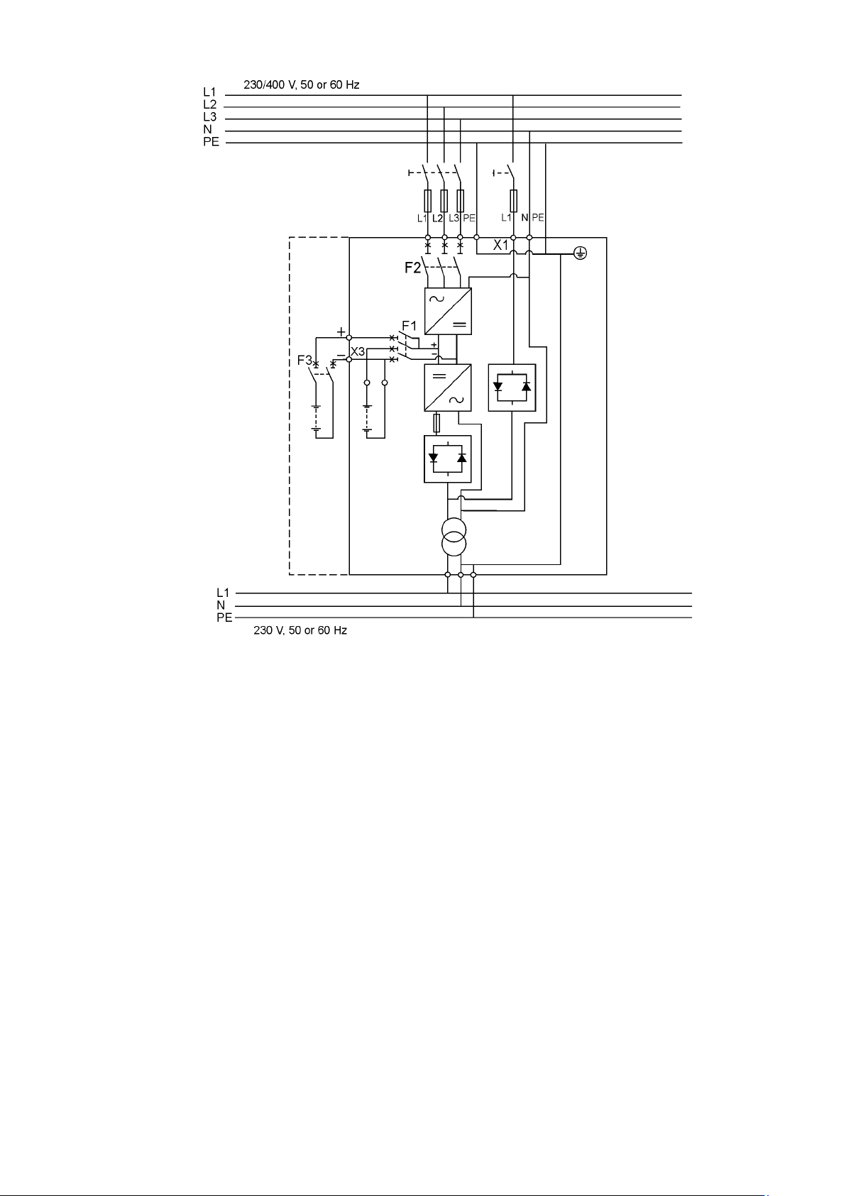
Figure 17. Wiring diagram of UPS NT-model (3-ph rectifier)