Eaton 9155 8-15 kVA.pdf - 第37页
UPS 8 – 15 kV A, 230V 50/60 Hz output User ’ s Guide 1 022403 Revision D 37 Note! Do not dispose of bat ter ies in a fire. The batt er ies may explode. Do not open or mutilate bat ter ies. Released electr olyte is har mfu…
UPS 8 – 15 kVA, 230V 50/60 Hz output
User’s Guide
1022403
Revision D
36
8. Maintenance
All operations inside the unit must be performed only by a service engineer from the
manufacturer or from an agent, authorised by the manufacturer.
The troubleshooting procedure gives simple remedial if a malfunction occurs in the UPS.
The operator should start the trouble shooting if there is an active alarm indicated on the LCD
screen. Service should be contacted if the active alarm is abnormal and displayed as a service
code.
Call service if you are not able to solve the problem.
Table 36. Typical alarms displayed in the LCD screen of the UPS unit.
Regular service/intervals
The UPS requires very little maintenance if installed in an appropriate environment. In order
to ensure maximum availability of the UPS, manufacturer recommends signing a proactive
service agreement with a local authorised service provider.
Table 37. Routine maintenance intervals recommended by the manufacturer.
Batteries
The condition of the batteries is crucial for operation. The UPS will indicate by audible and
visual alarms if the capacity of the battery bank has decreased. The UPS units are provided
with the automatic battery test and ABM management function to continuously monitor the
condition of the battery bank.
Servicing of batteries should be performed or supervised by personnel knowledgeable about
batteries and required precautions. When replacing batteries, replace with the same type and
number of batteries.
LCD display Description Action
Overload
The connected load needs more power
than the UPS is rated to provide. The
inverter or static bypass is supplying the
excessive load level.
Shut down the least important load that
is connected to the UPS. The UPS should
switch back to normal operation once the
load level is acceptable.
Battery test failed Your batteries are detected to be faulty.
Batteries should be replaced and you need
to contact the local office or representative
of the UPS manufacturer.
Battery low
The UPS is operating in stored energy
mode. It will shut down soon due to low
battery voltage.
Make controlled shutdown of the protected
load immediately to prevent loss of data.
On battery
The UPS is operating in stored energy
mode.
Save your data and perform a controlled
shutdown of your server load.
Overtemperature High UPS temperature is detected.
Check that fans are operational and ventila-
tion holes are not blocked. Make sure the
ambient temperature is not excessive
Maintentenance Interval
Batteries change ~ 3-5 years / service
Batteries test ~ 18 months / service
Cooling fan change ~ 5 years / service
UPS 8 – 15 kVA, 230V 50/60 Hz output
User’s Guide
1022403
Revision D
37
Note!
Do not dispose of batteries in a fire. The batteries may explode.
Do not open or mutilate batteries. Released electrolyte is harmful to the skin and
eyes. It may be toxic.
CAUTION
RISK OF EXPLOSION IF BATTERY IS REPLACED
BY AN INCORRECTED TYPE.
DISPOSE OF USED BATTERIES ACCORDING
TO THE INSTRUCTIONS
Cooling fan
The cooling fan lifespan of the UPS unit is about 60 000 operating hours. The actual lifespan
depends on the environment and ambient temperature.
Fan failure can be predicted by increasing noise from the fan bearings. The fan replacement is
recommended once this symptom starts appearing.
Do not use other than manufacturer’s specified spare parts.
LED Indicators
The UPS unit has (4) LEDs to indicate the status.
Table 38. Description of the LED indicators.
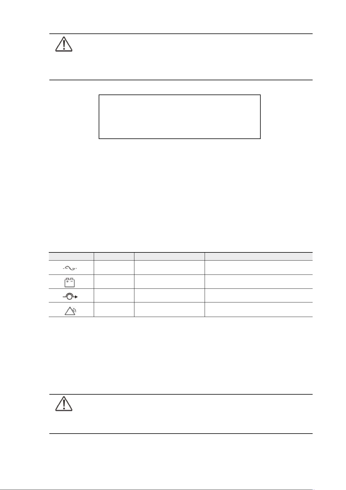
Maintenance bypass switch (MBS) operation
The maintenance bypass switch may be as standard or as optional in your system depending
on the ordered configuration. The operation of the MBS is allowed for a trained person only
who is familiar with the UPS behaviour and functions. The full UPS wiring diagram with a MBS
switch is presented in the installation part of the manual.
Note!
The MBS consist of three switches and failure to understand the correct sequence
may drop the critical load.
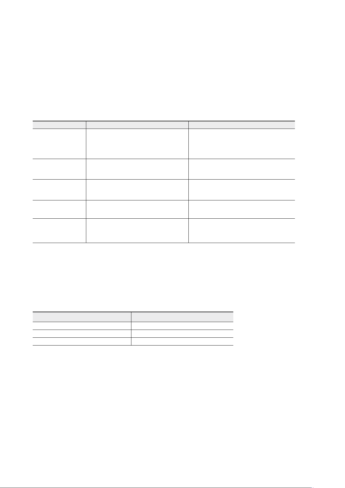
Graphical sign LED Description Note
Green UPS status is ok.
Blinking when a new notice message is
active.
Yellow 1 UPS is in battery mode
Yellow 2 UPS is in bypass mode
Red UPS has an active alarm
Blinking when new alarm is not reset and still
active.
UPS 8 – 15 kVA, 230V 50/60 Hz output
User’s Guide
1022403
Revision D
38
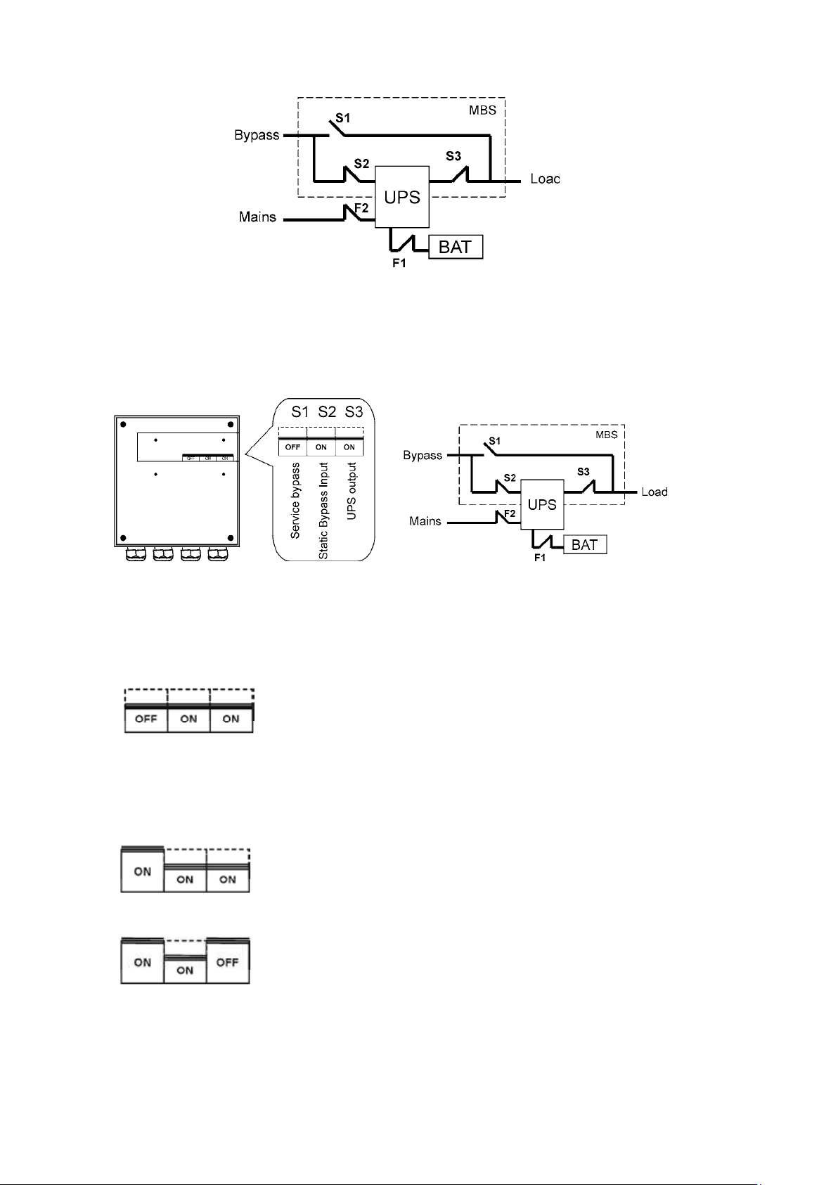
Figure 39. The normal positions of the three MBS switches.
Turn UPS from normal mode to mechanical bypass
The procedure to turn the UPS to mechanical bypass switch is described below.
Figure 40. The normal (UPS supplying the load) positions of the three MBS switches.
No break transfer from normal mode to Service Bypass:
1. The normal start position should be following:
2. Use LCD to turn the UPS on internal static bypass mode. Remember to verify the transfer
before proceeding the next step.
3. Remove the locking plate of the S1-3 switches.
4. Turn ON the S1 switch to bypass UPS:
5. Turn OFF the S3 switch to disconnect UPS output:
6. Use LCD to turn UPS OFF.
7. Turn
F1 battery breakers and F2 input to OFF position.