Eaton 9155 8-15 kVA.pdf - 第29页
UPS 8 – 15 kV A, 230V 50/60 Hz output User ’ s Guide 1 022403 Revision D 29 A S40 0 Rela y Module (optional) The Relay Module pro vides potential free relay interface for AS/400 connected computer s and industrial applic…
UPS 8 – 15 kVA, 230V 50/60 Hz output
User’s Guide
1022403
Revision D
28
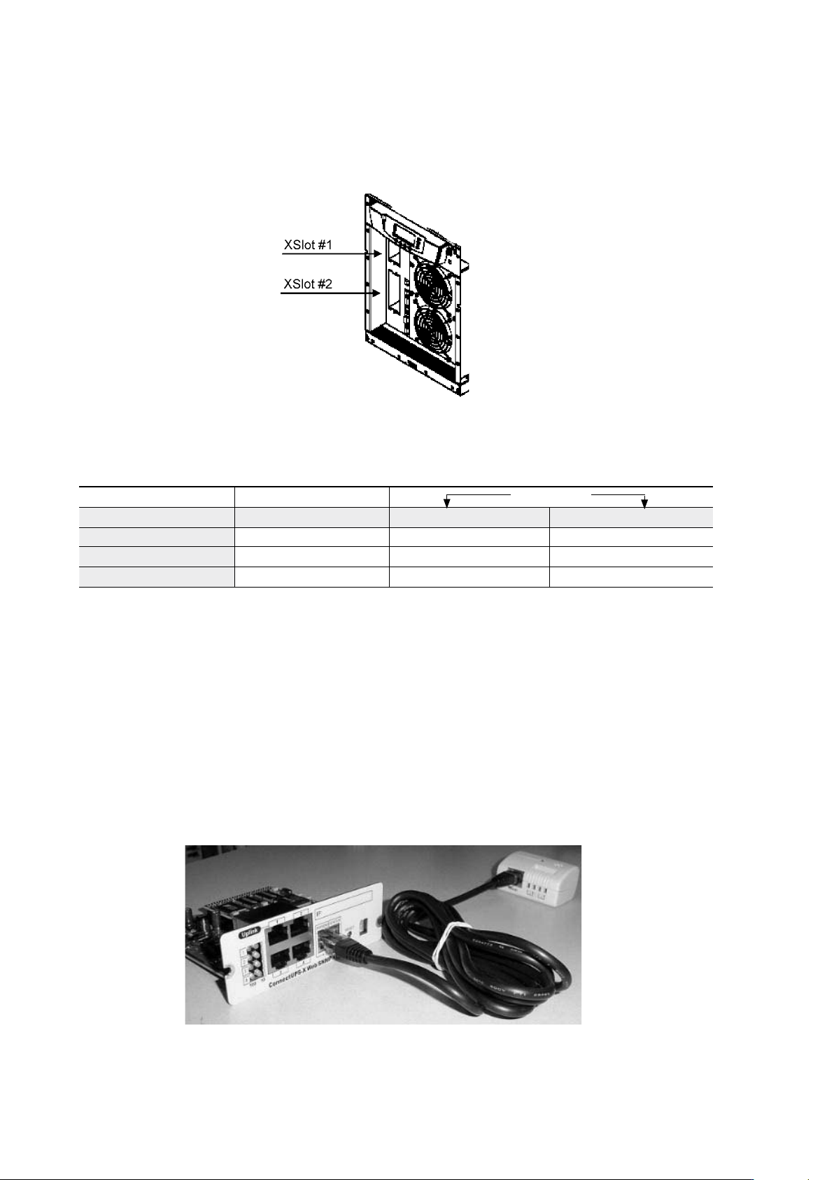
XSlot communication (option)
XSlot modules allow the UPS to communicate in a variety of networking environments and with
different types of devices. The UPS incorporates two (2) empty XSlot communication bays.
Figure 29. Location of empty XSlot bays.
The UPS supports two serial communication devices according to the table below.
Table 24. Typical XSlot configurations for UPS communication.
Web/SNMP Module (optional)
The module supports SNMP and HTTP compliant remote monitoring and shutdown for
the protected computer systems. It can be connected to a twisted-pair Ethernet network
(10/100BaseT) using an RJ45 connector.
The Web/SNMP module has a build-in switching hub that allows three (3) additional network
devices to be connected to the network without the requirement of additional network drops.
In addition, an Environmental Monitoring Probe can be requested from the UPS manufacturer
to obtain humidity, temperature, smoke alarm and security information. It is connected to the
communication port of the Web/SNMP module as option.
Figure 30. ConnectUPS-X Web/SNMP Module and Environmental Monitoring Probe.
Independent Multiplexed
Configuration XSlot #1 X-slot #2 Std. RS-232 port
Default #1 Any XSlot Module Any XSlot Module Not in use
Default #2 Any XSlot Module Relay Module Available
Default #3 Any XSlot Module Not in use Available
UPS 8 – 15 kVA, 230V 50/60 Hz output
User’s Guide
1022403
Revision D
29
AS400 Relay Module (optional)
The Relay Module provides potential free relay interface for AS/400 connected computers and
industrial applications. The relay interface supports both 15-pin D-sub connector and terminal
block connections up to four (4) potential free relays.
The relay contacts are rated for 1 A, 30 Vac or 200 mA, 60 Vdc, and they have a galvanic
isolation from the other circuits of the UPS unit.
Figure 31. AS400 Relay Module.
Single Serial Port Module (optional)
To establish communication between the UPS and a computer, connect your computer to the
UPS communication port using the supplied communication cable.
When the communication cable is installed, power management software can exchange data
with the UPS. The software polls the UPS for detailed information on the status of the power
environment. If a power emergency occurs, the software initiates the saving of all data and an
orderly shutdown of the equipment.
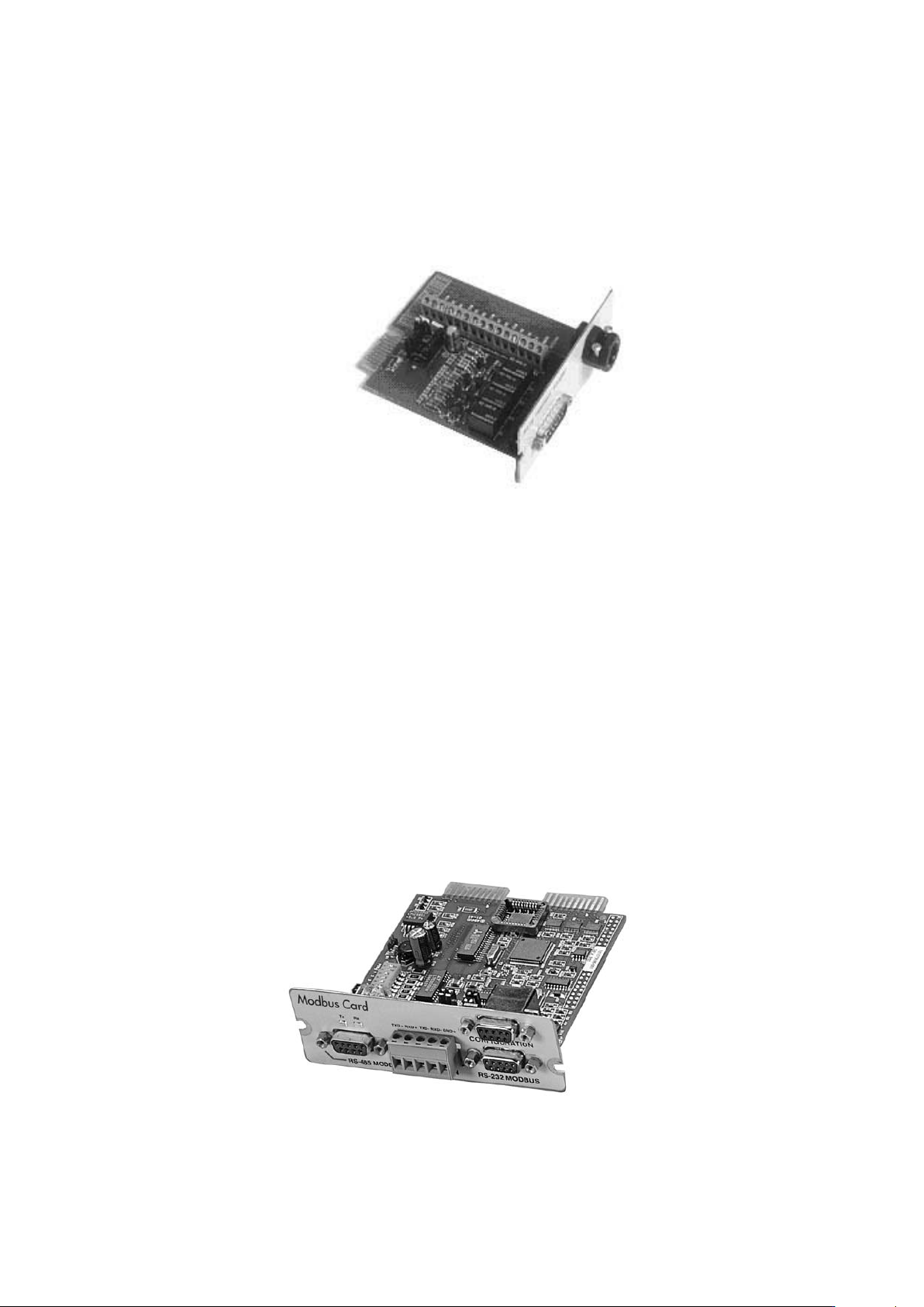
Modus/Jbus Module (optional)
The Modbus module provides monitoring and integration to the Building Management
Software (BMS) such as Wonderware. It features continuous and reliable communication
through isolated DB9 ports (RS485/RS232) or a terminal strip (RS485).
Figure 32. Modus/Jbus Module.

UPS 8 – 15 kVA, 230V 50/60 Hz output
User’s Guide
1022403
Revision D
30
7. User operations
The UPS has a four-button graphical LCD with backlight. It provides useful information about
the unit itself, load status, events, measurements, and settings.
The LCD backlight is switched on by pressing any button. It has a timeout that automatically
switches off after 15 minutes of inactivity.
Display functions
As default and after 15 minutes of inactivity the UPS is showing the selectable start screen:
1. Logo screen
2. Mimic screen (See User Settings on LCD screen)
The screen backlit has automatic shutdown after long period of inactivity. It will light up once a
button is pushed. The right side button will initiate the text to the screen. The scrolling through
the menu structure is done with buttons indicated by the images of the LCD screen. The
menu structure is shown in the table below. There are small differences in the menu structure
between single and parallel mode.
Parallel
Mode
Single
Mode
Main Menu Submenu Menu functions
I
x x UPS STATUS ->
UPS off / System normal / UPS supporting load / UPS on battery
/ UPS on bypass / +active alarms and notices / +battery status
(resting, charging, floating, not connected, discharging)
I
x x EVENT LOG -> Notice / Alarm
I
x x MEASUREMENTS
PARALLEL
SYSTEM
Parallel unit 1...4 kW/Parallel total kW
OUTPUT Voltage / Current / Frequency / Power
BATTERY Voltage / Current / Runtime
INPUT Voltage / Current / Frequency
BYPASS Voltage / Frequency
I
x x CONTROL -> Goto bypass / Battery test / Display test / Reset error state
I
x x SETTINGS
USER SETTINGS
Date / LCD contrast / Change language / Relay config / Signal
inputs / Serial port config / Parallel operation settings / Start
screen / User password / Audible alarms / Battery charging
method / +list of std. settings
SERVICE SET-
TINGS
Adjust parameters / Adjust events / Reset custom / Clear history
/ + modem call settings
I
x x IDENTIFICATION -> UPS Type / Part nro. / Serial nro / Revisions
I
x TURN UPS ON -> -
I
x TURN UPS OFF
I
x TURN SYSTEM ON
I
x TURN UPS OFF
I
x TURN SYSTEM OFF
Table 33. Menu map for display functions.