Eaton 9155 8-15 kVA.pdf - 第23页
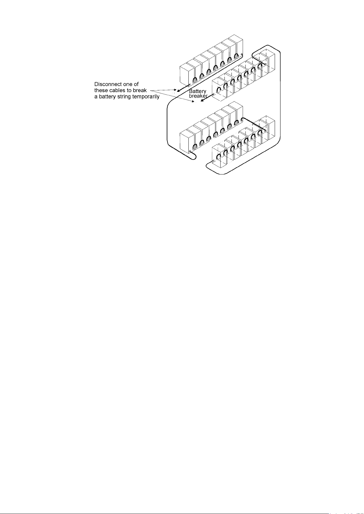
UPS 8 – 15 kV A, 230V 50/60 Hz output User ’ s Guide 1 022403 Revision D 23 Figure 25. T o minimise safety risk remove + or - cable from battery string before connecting UPS and EBCs.
UPS 8 – 15 kVA, 230V 50/60 Hz output
User’s Guide
1022403
Revision D
22
Warning!
If an internal battery string is installed and already connected to the terminal block
there is a danger of a lethal electric shock. Turn F1 battery breaker from the UPS
unit to OFF position and measure the voltage across the terminals to be 0 (zero)
before any operations with terminal X3.
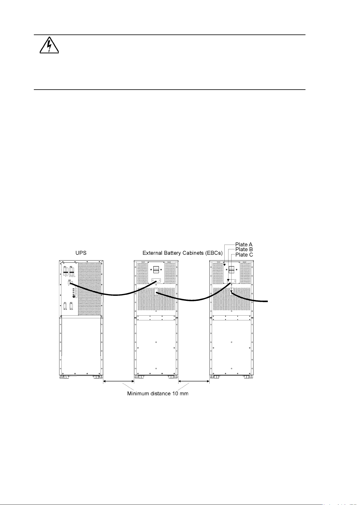
5. If the system consists two or more EBC connect first the EBCs parallel as follows:
a) Connect the cables to second EBC in the same way as guided in point four (4) of this
installation procedure.
b) Remove the cover plate C of the first EBC and connect cables to terminal block X6. Use the
cover plate C as a cable clamp.
6. When all the EBCs are connected parallel, make sure that F1 battery breaker is in OFF
position before connecting cables to terminal block X3 of the UPS unit. Otherwise the
terminal block X3 is live. To be on the safe side, measure the voltage across the terminals to
be 0 (zero).
7. After installation connect disconnected battery cables to strings, check that the removed
plates on right positions, remove safety wires from circuit breakers and turn breakers of
EBCs and the UPS to ON position.
8. Finally change the Number of 32 pcs. battery strings from User Settings. SETTINGS ->
USER SETTINGS -> NUMBER OF BATTERY STRINGS.
Figure 24. Connection of UPS and External Battery Cabinets
UPS 8 – 15 kVA, 230V 50/60 Hz output
User’s Guide
1022403
Revision D
23
Figure 25. To minimise safety risk remove + or - cable from battery string before connecting UPS and
EBCs.
UPS 8 – 15 kVA, 230V 50/60 Hz output
User’s Guide
1022403
Revision D
24
6. Software and connectivity
The software Suite CD-ROM that is bundled with the UPS contains software distributions and
documentation in CD format. Furthermore, the comprehensive connectivity option portfolio
includes Web/SNMP adapters for networked environments, Modem card for 24/7 remote
monitoring, ModBus/Jbus card for building management system integration, relay interface
cards for industrial and facilities use and RS-232 cards for serial communication to one or
multiple computers.
Communication cables
It is recommended that the control cables and power cables be installed on separate trays.
Where control cables will cross power cables make sure they are arranged at an angle as near
to 90 degrees as possible.
All control cables shall preferably be shielded. If the shield is grounded, this shall take place on
only one end of the cable.
The procedure for connecting the control cables is the following:
1. Remove the front cover by lifting the cover from the bottom outwards by releasing the
retaining clip. It’s located in the bottom part of the bezel.
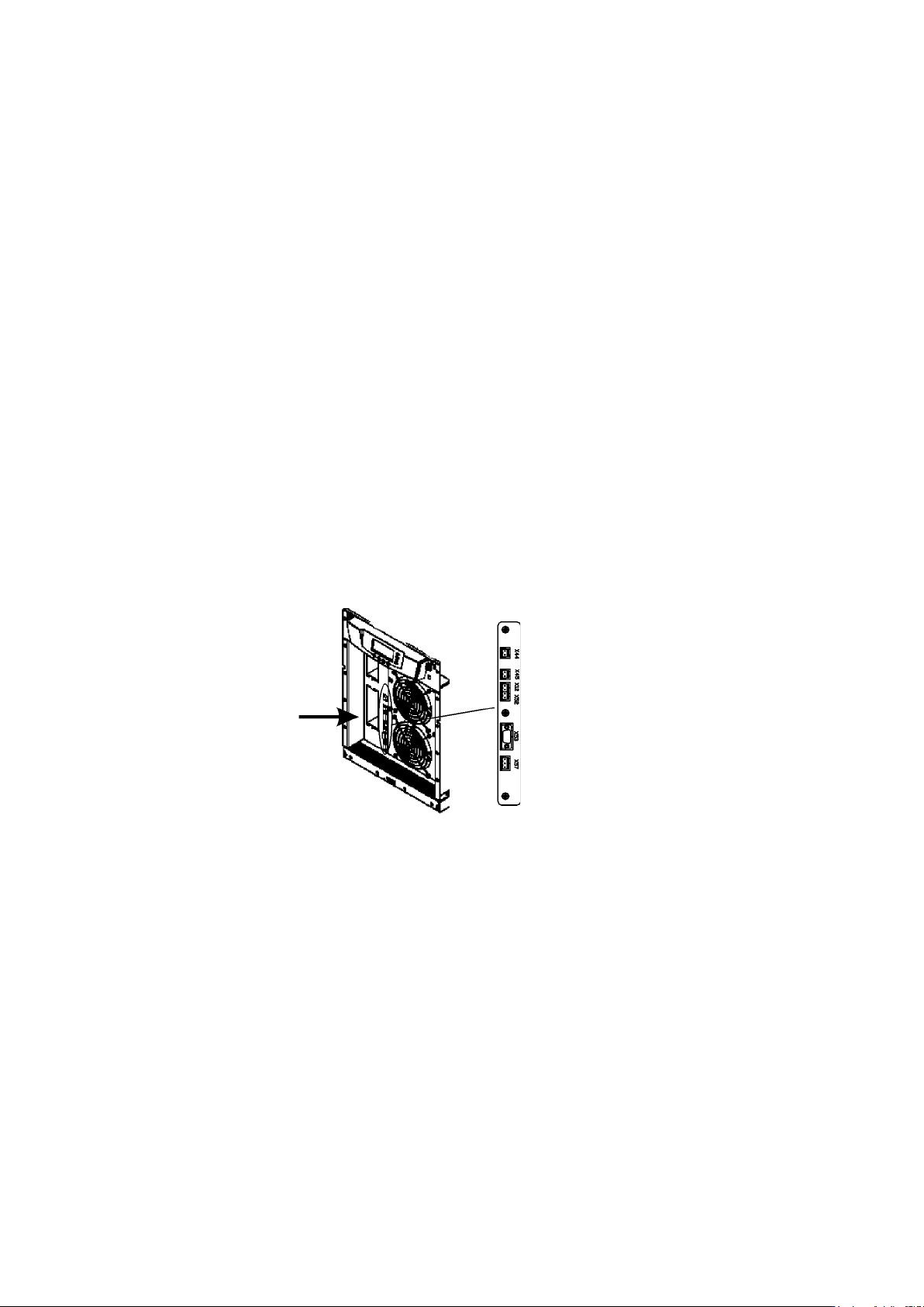
2. Locate the control terminal or XSlot module where you want to install the communications
cable.
Figure 26. Location of control cable terminals: Signal inputs (X44 & X45); EPO (NC (X12) & NO (X52));
RS-232 (X53); Relay output (X57).
Connection to the standard RS-232 port (X53)
The standard RS-232 interface uses 9-pin female D-sub connector. It shall be used with the
delivered cable for a computer or external modem connection. The data is transmitted with XCP
protocol that includes status and meters information about the UPS. The RS-232 port has the
following format:
• Communication speed 19200 bps*
• Data bits 8
• Parity None
• Stop bits 1
• Handshake None
* Communication speed can be changed via LCD menu