Eaton 9155 8-15 kVA.pdf - 第27页
UPS 8 – 15 kV A, 230V 50/60 Hz output User ’ s Guide 1 022403 Revision D 27 W ar ning! The r elay contacts must not be dir ectly connected to mains r elated cir cuits. Reinfor ced insulation to the mains is r equired. Pr…
UPS 8 – 15 kVA, 230V 50/60 Hz output
User’s Guide
1022403
Revision D
26
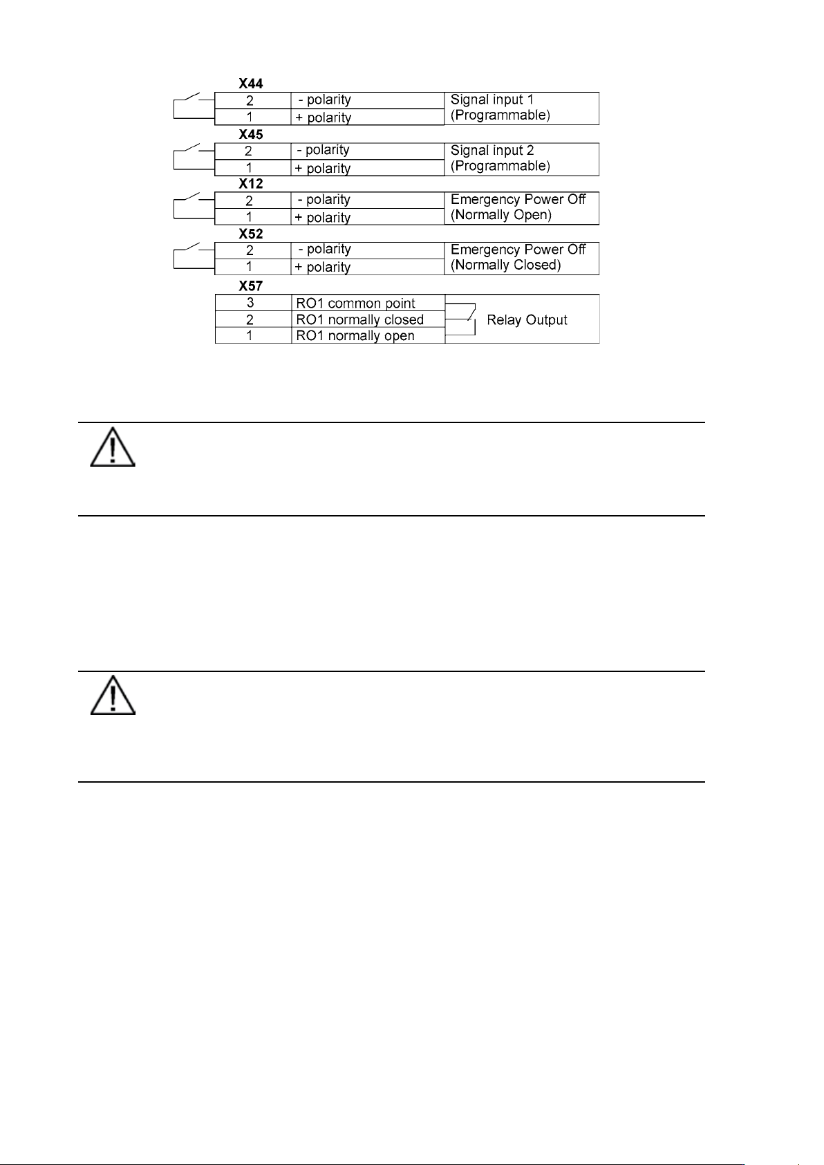
Figure 28. External control cable connections to the UPS.
Note!
Pay attention to proper polarity if one is using a semiconductor switch type. A relay
or other mechanical control is a preferred method.
Emergency Power Off (EPO)
This input is used to shut down the UPS from a distance. This feature can be used for
emergency power down. There are two modes of operation, normally closed at X52 and
normally open at X12. Remote shut down terminal X52 pins 1 and 2 are as factory default linked
(X12 is open). When the loop on X52 is opened, the logic circuitry will immediately shut down
the UPS output and open the battery breaker (F1).
Note!
EPO does not necessarily disconnect supply to load when unit is on internal or
external bypass. Quaranteed disconnection of bypass supply has to be through a
separate disconnect switch located in the supplying switchgear cabinet.
In order to have the UPS running again pins 1 and 2 of connector X52 have to be reconnected and
the UPS started manually. The pins must be shorted in order to keep the UPS running. Maximum
resistance is 10 ohm. The EPO shall not be galvanically connected to any mains connected circuits.
Reinforced insulation to the mains is required. See also “Start-up after EPO”.
If the use of normally open EPO operation is desired, the loop on X52 has to be retained and the
normally open EPO switch connected to X12. Operation is as above.
Relay outputs
The UPS incorporates a programmable relay output with potential free contacts at X57 for remote
alarm indications. It is rated for max. 30 VAC 1 A or 60 VDC 0,2 A nominal values. Additional (4)
relay outputs can be obtained with the XSlot compatible AS/400 Relay Module (optional). For
more information see the section “Using relay outputs”

UPS 8 – 15 kVA, 230V 50/60 Hz output
User’s Guide
1022403
Revision D
27
Warning!
The relay contacts must not be directly connected to mains related circuits.
Reinforced insulation to the mains is required.
Programmable signal inputs
The UPS incorporates two programmable inputs (X44, X45). Use of a non-polar (relay) control
input is recommended. The pins must be shorted with maximum resistance of 10 ohm in order
to activate the specific input.
Note!
Please note the polarity of the inputs as indicated in the external control
connections if used with a polarity control.
The default and programmable settings for the signal inputs are
a) Disable Bypass Operation
If active the automatic transfer to the static bypass is prevented.
b) Charger off
If active the batteries charging is disabled. In case of mains power outage the discharge of
batteries is supported.
c) Remote ON/OFF
If active the UPS output turns off regardless of mode of operation. Auxiliary power, fan,
communications and rectifier/battery charger shall remain functional. Restart initiated
immediately when inactive.
d) Request Bypass
If active the UPS transfers to bypass if bypass voltage, frequency and synchronisation are ok.
e) Request Normal
If active the UPS transfers to inverter operation if not prohibited by EPO or alarm condition.
f) Force Bypass
If active the UPS is forced to static bypass operation regardless of the bypass status.
g) External Battery Breaker Status
If active the UPS knows that the batteries are disconnected.
h) Building alarm 1-6
These can be activated separately or at the same time with other building alarms.
i) Not in use (default)
j)
Shutdown
If active the UPS will shutdown immediately.
k) Delayed Shutdown
If active the UPS will shutdown after user configurable delay time. Restart initiated
immediately when inactive.
l) Normal/Bypass
If active the UPS transfers to bypass if ok. If inactive the UPS transfers to inverter when
possible.
m) Output transformer over temperature
If active the UPS output turns off after user configurable delay time.
n) Input transformer over temperature without bypass
If active the UPS will start to operate on battery or shutdown when batteries not available after
one minute delay.
o) Input transformer over temperature with bypass
If active the UPS will start to operate on battery or transfer to bypass after one minute delay.
UPS 8 – 15 kVA, 230V 50/60 Hz output
User’s Guide
1022403
Revision D
28
XSlot communication (option)
XSlot modules allow the UPS to communicate in a variety of networking environments and with
different types of devices. The UPS incorporates two (2) empty XSlot communication bays.
Figure 29. Location of empty XSlot bays.
The UPS supports two serial communication devices according to the table below.
Table 24. Typical XSlot configurations for UPS communication.
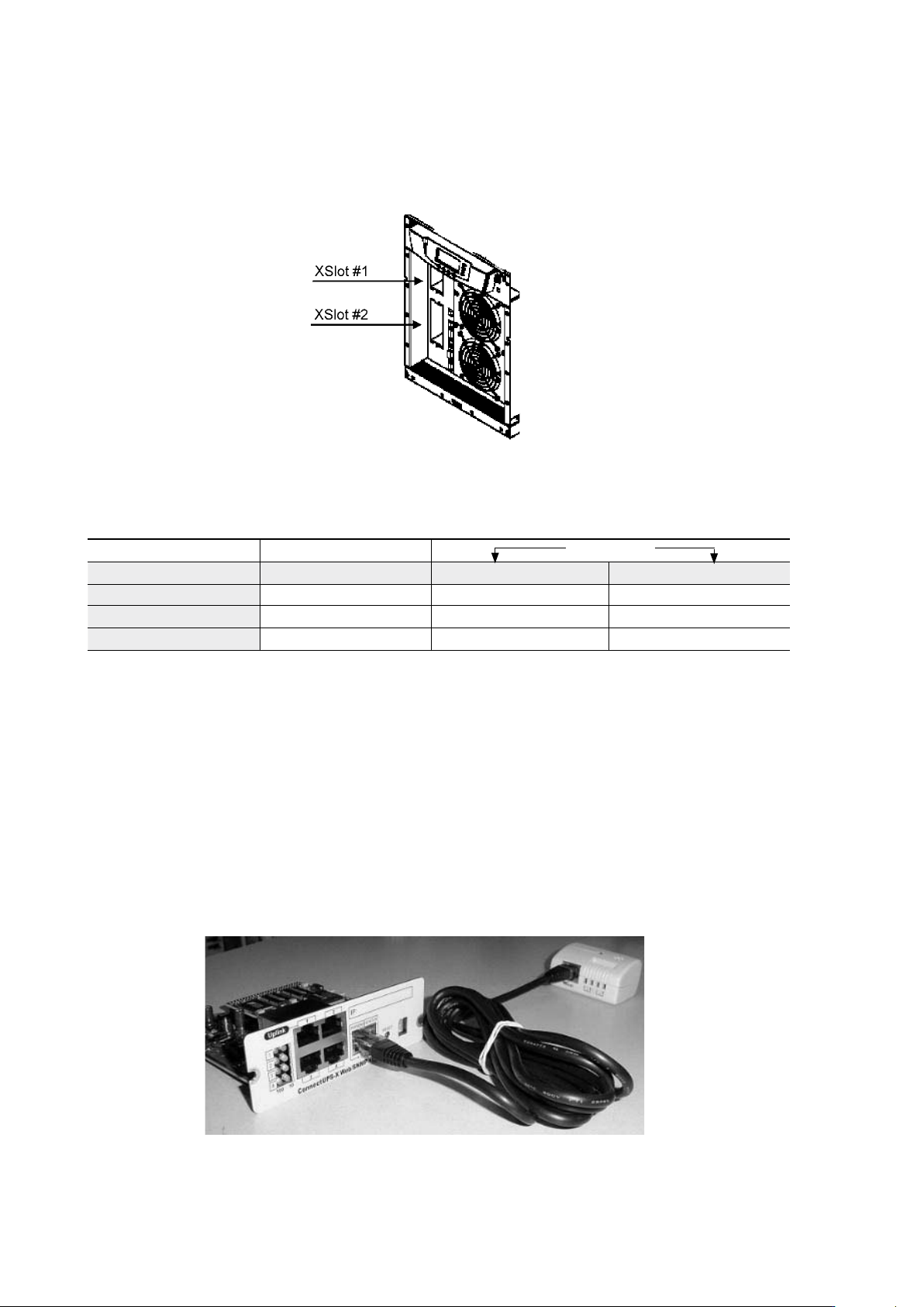
Web/SNMP Module (optional)
The module supports SNMP and HTTP compliant remote monitoring and shutdown for
the protected computer systems. It can be connected to a twisted-pair Ethernet network
(10/100BaseT) using an RJ45 connector.
The Web/SNMP module has a build-in switching hub that allows three (3) additional network
devices to be connected to the network without the requirement of additional network drops.
In addition, an Environmental Monitoring Probe can be requested from the UPS manufacturer
to obtain humidity, temperature, smoke alarm and security information. It is connected to the
communication port of the Web/SNMP module as option.
Figure 30. ConnectUPS-X Web/SNMP Module and Environmental Monitoring Probe.
Independent Multiplexed
Configuration XSlot #1 X-slot #2 Std. RS-232 port
Default #1 Any XSlot Module Any XSlot Module Not in use
Default #2 Any XSlot Module Relay Module Available
Default #3 Any XSlot Module Not in use Available