Eaton 9155 8-15 kVA.pdf - 第8页
UPS 8 – 15 kV A, 230V 50/60 Hz output User ’ s Guide 1 022403 Revision D 8 3. Planning bef or e installation The equipment must be installed in upright position. The equipment requires space to front and bac k to enable …
UPS 8 – 15 kVA, 230V 50/60 Hz output
User’s Guide
1022403
Revision D
7
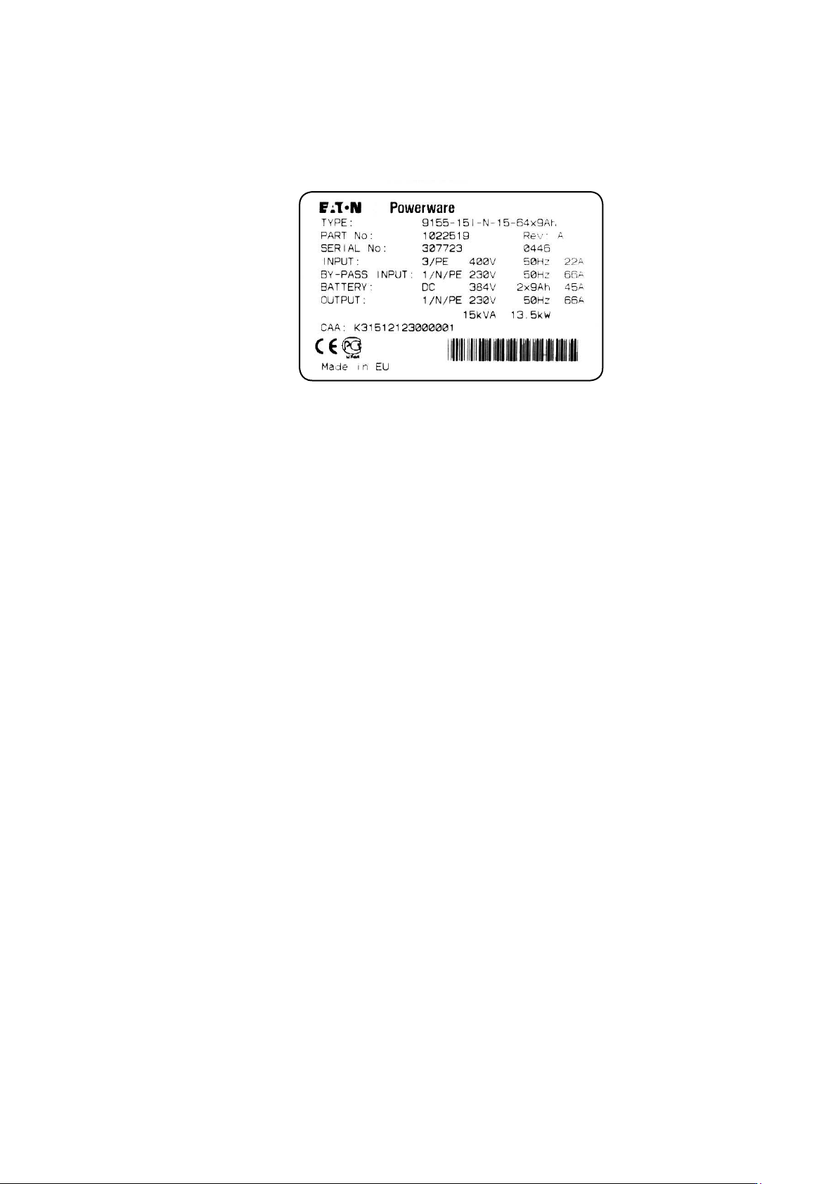
Check the information on the type designation label of the equipment to verify that the unit is of
the correct type. The type designation label includes ratings, a CE marking, a type code, a part
number and a serial number. The serial number is important when making inquiries. It allows
individual recognition of the equipment.
Figure 2. Type designation label.
UPS 8 – 15 kVA, 230V 50/60 Hz output
User’s Guide
1022403
Revision D
8
3. Planning before installation
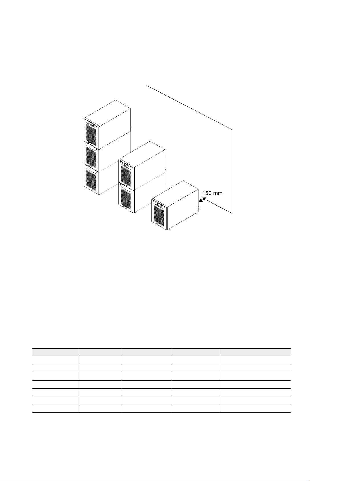
The equipment must be installed in upright position. The equipment requires space to front and
back to enable cooling airflow, service and maintenance. All cooling air enters at front and exits
at unit rear. The required min. clearance from unit rear to an obstruction is 150 mm.
Figure 3. Ventilation space around the equipment.
It is required to arrange ventilation of the UPS room. Sufficient amount of air cooling is needed
to keep the max. room temperature rise at desired level:
• Temperature rise of max. +5°C requires the airflow of 600 m
3
per 1 kW of losses.
• Temperature rise of max. +10°C requires the airflow of 300 m
3
per 1 kW of losses.
An ambient temperature of 15 to 25 Celsius degrees is recommended to achieve a long life of
the UPS and batteries. The cooling air entering the UPS must not exceed +40 °C. Avoid high
ambient temperature, moisture and humidity.
The floor material should be non-flammable and strong enough to support the heavy load. The
UPS has (4) leveling feet that should be used when finalising the installation. The diameter of a
single leveling foot is 1 inch (25.4 mm).
Table 4. The floor surface must tolerate these loading.
Equipment Weight Point Distributed Note
UPS+1BAT 155 kg 7.75 kg/cm
2
738 kg/m
2
Batteries installed.
UPS+2BAT 265 kg 13.25 kg/cm
2
1262 kg/m
2
Batteries installed.
UPS 50 kg 2.50 kg/cm
2
238 kg/m
2
No Batteries.
UPS+1BAT 65 kg 3.25 kg/cm
2
310 kg/m
2
No Batteries installed.
UPS+2BAT 80 kg 3.95 kg/cm
2
382 kg/m
2
No Batteries installed.
2BAT 195 kg 9.75 kg/cm
2
929 kg/m
2
Batteries installed.
3BAT 310 kg 15.50 kg/cm
2
1476 kg/m
2
Batteries installed.
UPS 8 – 15 kVA, 230V 50/60 Hz output
User’s Guide
1022403
Revision D
9
4. Cabinet installation
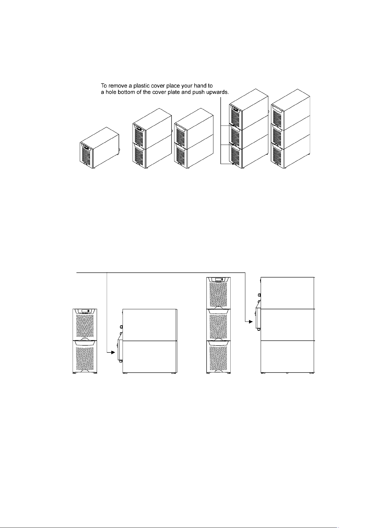
The required distance for UPS units next to each other is ten millimetres. The same applies to
the optional battery cabinets that should be installed next to the UPS cabinet.
Figure 5. UPS and external battery cabinets.
The UPS family has several alternative battery cabinets and configurations depending on the
selected back-up time and quality of batteries.
Maintenance bypass switch
The maintenance bypass switch (MBS) shall be mounted in back of the UPS battery
compartment. It can be ordered factory installed.
Figure 6. Instructions for locating the mechanical bypass switch.
Please fix the switch MBS to the wall (din rail) or to the back of the UPS as shown below.