Eaton 9155 8-15 kVA.pdf - 第46页
UPS 8 – 15 kV A, 230V 50/60 Hz output User ’ s Guide 1 022403 Revision D 46 XSlot Hot S ync card: installing and wir ing T o enable parallel operation all the UPSs in the system need the XSlot Hot Sync card (see Figure b…
UPS 8 – 15 kVA, 230V 50/60 Hz output
User’s Guide
1022403
Revision D
45
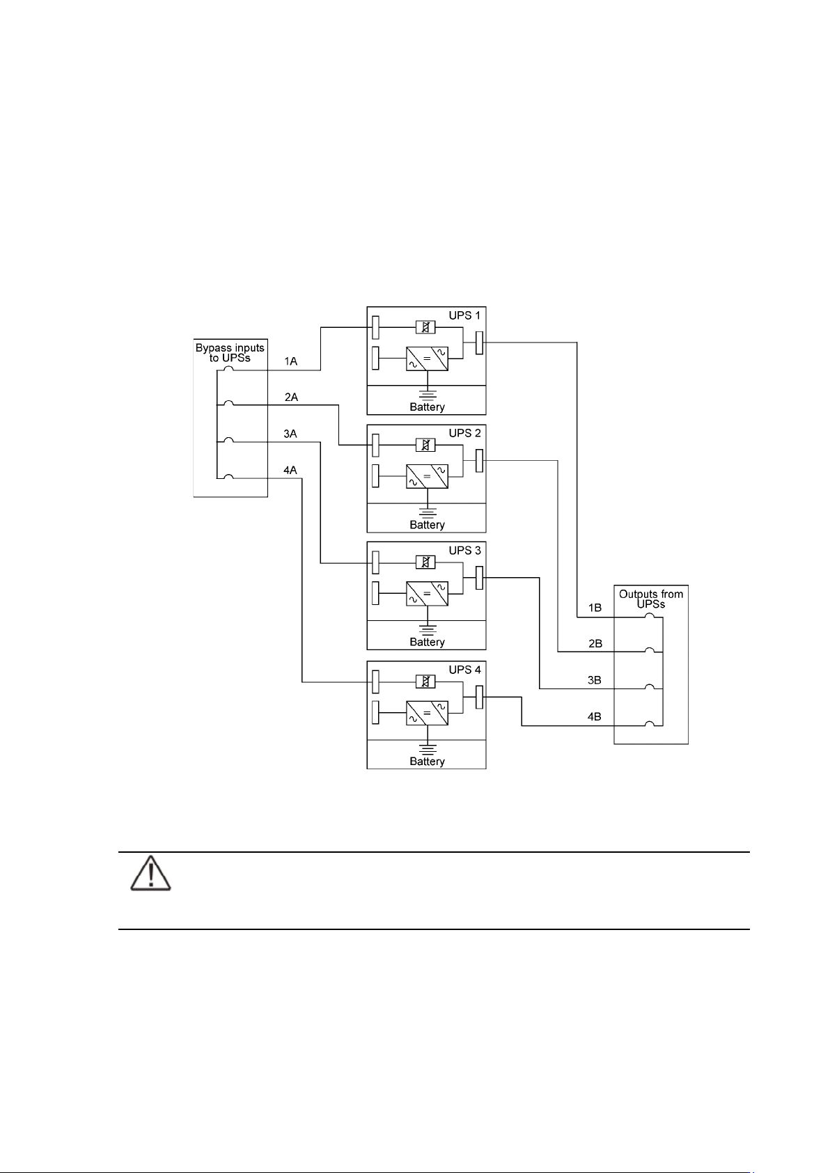
Required parallel system wiring length should be in accordance with the following rule, as
referenced to the diagram below to ensure approximately equal current sharing when in static
bypass mode (see Figure below:
Total length of 1A + 1B = Total length of 2A + 2B
= Total length of 3A + 3B
= Total length of 4A + 4B
This rule has a tolerance of approximately ± 10% for the combined input and output wire
lengths. If installing only two UPS modules, this requirement is no longer required as each
UPS is capable of supporting the full bypass requirement. However, this would preclude future
expansion.
Figure 48. Bypass wiring diagram and cable length notes.
Note!
Signal input cables need to be connected to all UPS when used.
UPS 8 – 15 kVA, 230V 50/60 Hz output
User’s Guide
1022403
Revision D
46
XSlot Hot Sync card: installing and wiring
To enable parallel operation all the UPSs in the system need the XSlot Hot Sync card (see
Figure below) installed into an open XSlot on the front of the UPS (see chapter XSlot
communication from the UPS’s User’s Guide).
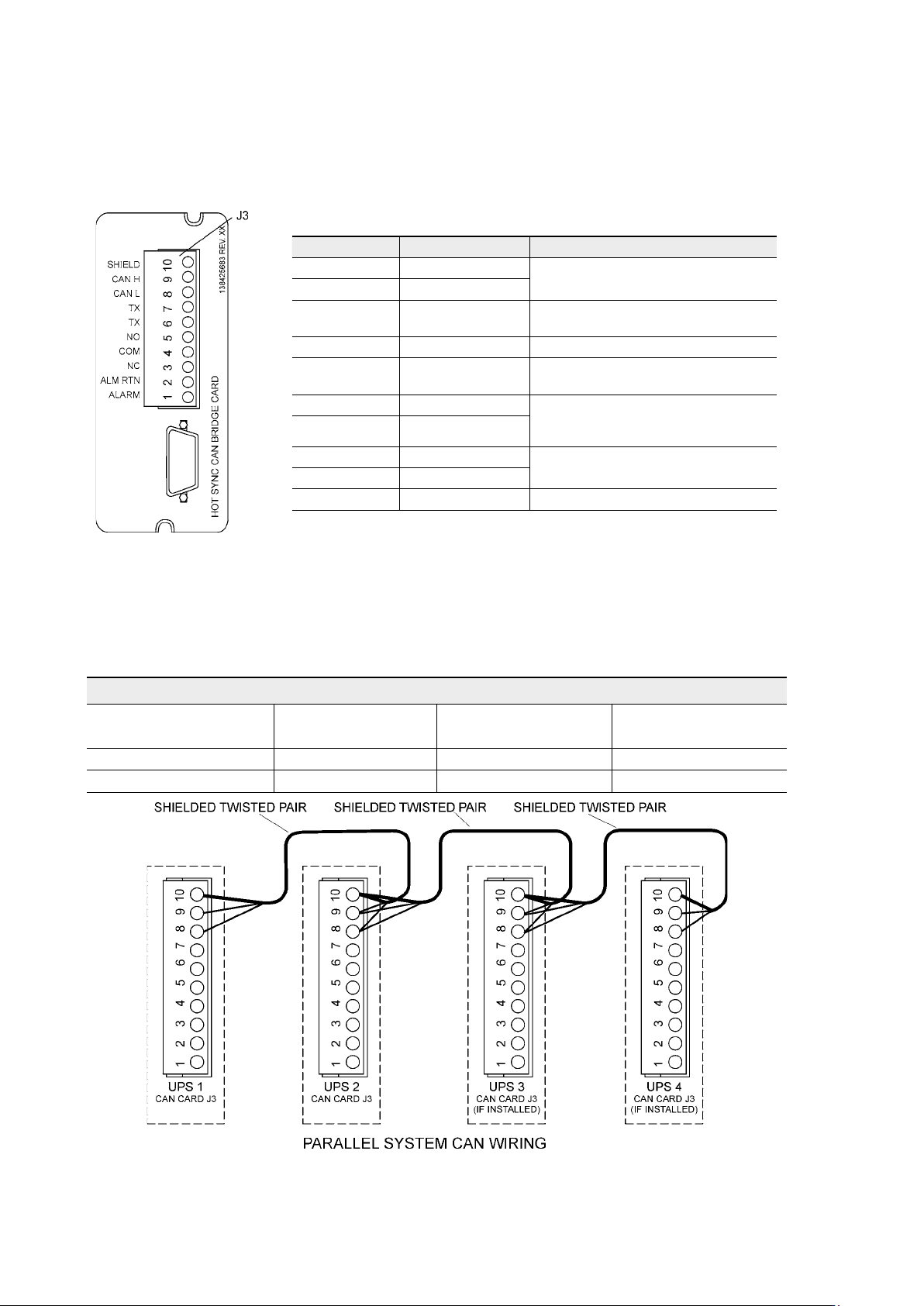
Figure 49. XSlot Hot Sync card and terminal interface
The Hot Sync communication wiring procedure should be done with shielded twisted pair
(STP) as presented in the figure below. The maximum length of the cable is 40 m with shield
connected to the terminal pin 10 from end of the both cables. Pay attention that you don’t mix
the polarity among the UPS modules.
Figure 50. Communication cabling wiring
Terminal J3 Name Description
1 Alarm
Programmable UPS alarm. Activated
by a remote dry contact closure
2 Alarm Rtn
3 Alarm Relay NC
Normally-closed contact opens when
UPS is on bypass.
4 Alarm Relay Com Bypass contact return.
5 Alarm Relay NO
Normally-open contact closes when
UPS is on bypass.
6 TX Remote Monitor Panel (RMP). Relay
Interface Module (RIM, or Supervisory
Contact Module (SCM) Connections.
7 TX
8 CAN L
Controller Area Network (CAN) Input
for parallel operation.
9 CAN H
10 Shield
Communication Wiring Termination
From UPS 1 CAN card To UPS 2 CAN card
To UPS 3 CAN Card
(If installed)
To UPS 4 CAN Card
(If installed)
J3-8 (L) J3-8 (L) J3-8 (L) J3-8 (L)
J3-9 (H) J3-9 (H) J3-9 (H) J3-9 (H)
UPS 8 – 15 kVA, 230V 50/60 Hz output
User’s Guide
1022403
Revision D
47
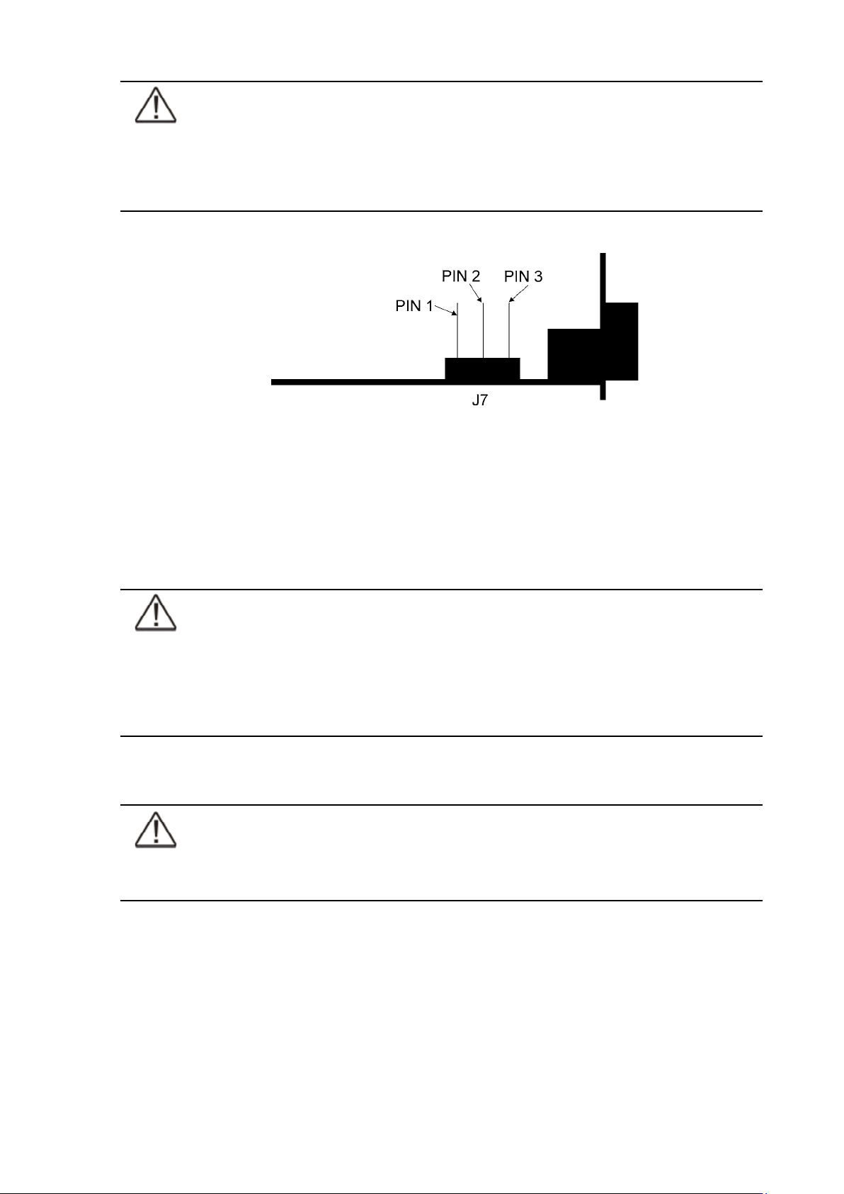
Note!
XSlot Hot Sync card has built-in termination resistor enabled by a jumper J7. The
default jumper setting without termination resistor is J7: Pin 2-3. The first and the
last UPS modules should have the termination resistor enabled by connecting Pins
1 and 2 with the jumper J7.
Figure 51. XSlot HotSync card and jumper settings: Resistor ON: PIN 1 and PIN 2 connected, No
resistor: PIN 2 and PIN 3 connected (default setting)
Parallel operations
Start-up
Note!
Before start-up make sure that UPS installations have been carried out correctly
and ground connections of both UPS units and parallel module have been
connected. Check also that the XSlot Hot Sync cards are installed correctly
and the communication line between UPSs is connected according to figure
Communication cabling wiring.
When installation is completed correctly the start procedure can be started.
Note!
If some settings are changed from User settings the same changes need to be done
separately to all of the UPSs in the system.