Eaton 9155 8-15 kVA.pdf - 第38页
UPS 8 – 15 kV A, 230V 50/60 Hz output User ’ s Guide 1 022403 Revision D 38 Figure 39. The normal positions of the three MBS switches. T ur n UPS fr om nor mal mode t o mec hanical b ypass The procedure to turn the UPS t…
UPS 8 – 15 kVA, 230V 50/60 Hz output
User’s Guide
1022403
Revision D
37
Note!
Do not dispose of batteries in a fire. The batteries may explode.
Do not open or mutilate batteries. Released electrolyte is harmful to the skin and
eyes. It may be toxic.
CAUTION
RISK OF EXPLOSION IF BATTERY IS REPLACED
BY AN INCORRECTED TYPE.
DISPOSE OF USED BATTERIES ACCORDING
TO THE INSTRUCTIONS
Cooling fan
The cooling fan lifespan of the UPS unit is about 60 000 operating hours. The actual lifespan
depends on the environment and ambient temperature.
Fan failure can be predicted by increasing noise from the fan bearings. The fan replacement is
recommended once this symptom starts appearing.
Do not use other than manufacturer’s specified spare parts.
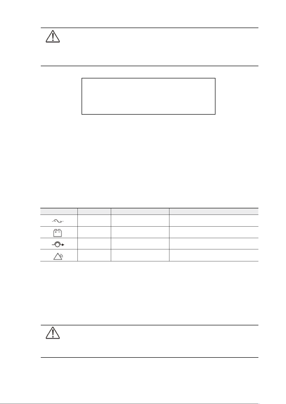
LED Indicators
The UPS unit has (4) LEDs to indicate the status.
Table 38. Description of the LED indicators.
Maintenance bypass switch (MBS) operation
The maintenance bypass switch may be as standard or as optional in your system depending
on the ordered configuration. The operation of the MBS is allowed for a trained person only
who is familiar with the UPS behaviour and functions. The full UPS wiring diagram with a MBS
switch is presented in the installation part of the manual.
Note!
The MBS consist of three switches and failure to understand the correct sequence
may drop the critical load.
Graphical sign LED Description Note
Green UPS status is ok.
Blinking when a new notice message is
active.
Yellow 1 UPS is in battery mode
Yellow 2 UPS is in bypass mode
Red UPS has an active alarm
Blinking when new alarm is not reset and still
active.
UPS 8 – 15 kVA, 230V 50/60 Hz output
User’s Guide
1022403
Revision D
38
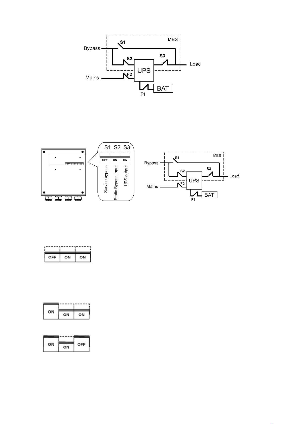
Figure 39. The normal positions of the three MBS switches.
Turn UPS from normal mode to mechanical bypass
The procedure to turn the UPS to mechanical bypass switch is described below.
Figure 40. The normal (UPS supplying the load) positions of the three MBS switches.
No break transfer from normal mode to Service Bypass:
1. The normal start position should be following:
2. Use LCD to turn the UPS on internal static bypass mode. Remember to verify the transfer
before proceeding the next step.
3. Remove the locking plate of the S1-3 switches.
4. Turn ON the S1 switch to bypass UPS:
5. Turn OFF the S3 switch to disconnect UPS output:
6. Use LCD to turn UPS OFF.
7. Turn
F1 battery breakers and F2 input to OFF position.
UPS 8 – 15 kVA, 230V 50/60 Hz output
User’s Guide
1022403
Revision D
39
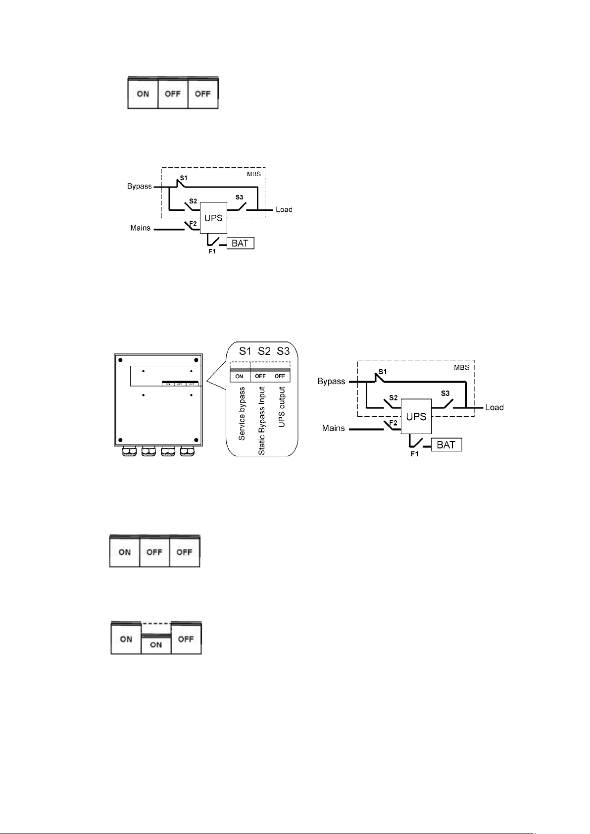
8. Turn OFF the S2 switch to disconnect UPS bypass input:
9. Remount the locking plate of the S1-3 switches to the position to prevent the use of them.
10. UPS is now in the mechanical bypass mode, see below:
Turn UPS from mechanical bypass to normal mode
The procedure to turn the UPS back to normal mode is described below.
Figure 41. The service (bypass supplying the load) positions of the three MBS switches.
No break transfer from Mechanical Bypass to normal mode:
1. The normal start position should be following:
2. Remove the locking plate of the S1-3 switches.
3. Turn ON S2 switch to connect bypass input to UPS:
4. Turn the F1 battery and F2 input breakers to ON position.
5. Use LCD to “Turn UPS on” and wait until fully started.
- Make sure the UPS is not displaying alarms or notices alarm with the green LED lit.
- You may verify the output voltage from the meters screen of the LCD.
6. Use LCD to transfer the UPS to internal static bypass. Remember to verify the transfer
before proceeding the next step.