00195398-0103-AI-01005Paket_DE_EN.pdf - 第45页
Asse mb ly In st ruct i on s 0100 5- Pac ket Edi t io n 12 /200 7 45 3.5 Safety instru ction s W ARNING The saf ety instructions in the c hap ter Operational Safety in the ope rating and serv ice manua l take priority . …
Assembly Instructions 01005-Packet
Edition 12/2007
44
3.2.3 Tools and Equipment
– Standard tool
3.3 Restrictions
– The 01005-package is only designed for use with D1/D2/D4-machines equipped with a C&P12
DLM3 head.
– The maximum length of the PCB is 230 mm.
– When using D4-machines, assembly must only take place in placement area 1 (PA1).
– Feeder with 01005-components may not be setup too far from the gantry suspension. De-
pending on the gantry suspension, the first six 3x8-feeder at maximum can be used for setup.
– If 01005-components are processed, the benchmark performance will drop approx. 22%.
3.4 Overview of Procedure
– Standard OnSite-MFU in order to document the original state of the machine before retrofitting.
– Replacement of existing component camera with new component camera.
– Replacement of existing sleeves with three new "SP12 sleeves comp." / 270 degree partition.
– Assignment of serial number for this sleeve to the segment.
– For SIPLACE D4 only: adjustment of changeover table height.
– Measurement of camera and placement head in SITEST - remeasure complete machine if
necessary.
– MFU with retrofitted machine using 01005 travel profile 33/34.
– Configuration of setup and component shape in SIPLACE Pro.
– Configuration at station computer.

Assembly Instructions 01005-Packet
Edition 12/2007
45
3.5 Safety instructions
WARNING
The safety instructions in the chapter Operational Safety in the operating and service manual take
priority. 3
The SIPLACE machines are supplied with line voltage.
Parts of the system carry potentially lethal voltages! These voltages are present at certain
assemblies inside the machine frame even when the machine is switched off at the main switch!
Incorrect handling of the placement system or touching live machine parts can therefore result in
death, severe injury or considerable damage to equipment.
Before you perform any work on the machine, shut down the operating system and then ensure
that the machine is switched off at the main switch and is disconnected from the line supply . In
addition, the compressed air supply must be turned off at the main valve of the compressed air
unit, in the machine frame, and the compressed air lines must be bled by actuating the needle
valve on the compressed air unit.
The area around the linear motors presents a risk of lethal injuries to persons wearing heart
pacemakers. Observe the instructions in Chapter "Special safety instructions for working in the
vicinity of powerful magnetic fields" in the operating and service manuals.
Always follow the applicable accident prevention and DIN regulations, as well as the safety regu-
lations specific to your country.
Read and observe the instructions about residual voltages in Chapter "Operational Safety".
Always observe the ESD regulations described in Chapter "Operational Safety" of the operating
manual.
While performing retrofitting work, always secure the machine to prevent unauthorized reactiva-
tion or access by unauthorized persons, as described in Chapter "Locking the Machine...
".
There is an additional, high risk of accidents when working with the SITEST program. SITEST
may therefore only be started by specially authorized and trained persons.
3
Assembly Instructions 01005-Packet
Edition 12/2007
46
3.6 Working Mechanically with MFU
3.6.1 Executing Standard On-Site MFU
Before retrofitting can be executed, the machine capability must be measured in order to docu-
ment the original machine state before retrofitting. 3
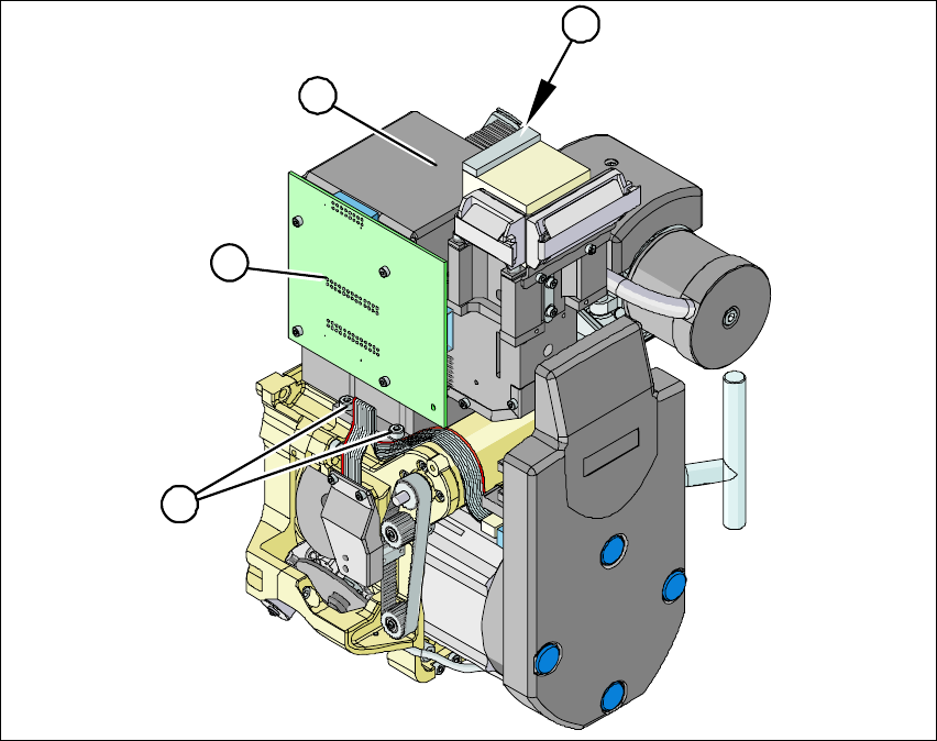
3.6.2 Installing / Removing the Component Camera
Fig. 24 Installing /removing the component camera
Æ Loosen the flat ribbon cable and strain reliefs, where necessary, so that the component camera
can be accessed.
2
3
3
1