00195398-0103-AI-01005Paket_DE_EN.pdf - 第46页
Asse mb ly In st ruct i on s 0100 5- Pac ket E di tio n 1 2 /20 07 46 3. 6 W ork ing Mec hani call y with M FU 3.6. 1 Execu ting S t a ndard On-S ite MFU Before ret rofitting can be ex ecuted, the mac hine c apability m …

Assembly Instructions 01005-Packet
Edition 12/2007
45
3.5 Safety instructions
WARNING
The safety instructions in the chapter Operational Safety in the operating and service manual take
priority. 3
The SIPLACE machines are supplied with line voltage.
Parts of the system carry potentially lethal voltages! These voltages are present at certain
assemblies inside the machine frame even when the machine is switched off at the main switch!
Incorrect handling of the placement system or touching live machine parts can therefore result in
death, severe injury or considerable damage to equipment.
Before you perform any work on the machine, shut down the operating system and then ensure
that the machine is switched off at the main switch and is disconnected from the line supply . In
addition, the compressed air supply must be turned off at the main valve of the compressed air
unit, in the machine frame, and the compressed air lines must be bled by actuating the needle
valve on the compressed air unit.
The area around the linear motors presents a risk of lethal injuries to persons wearing heart
pacemakers. Observe the instructions in Chapter "Special safety instructions for working in the
vicinity of powerful magnetic fields" in the operating and service manuals.
Always follow the applicable accident prevention and DIN regulations, as well as the safety regu-
lations specific to your country.
Read and observe the instructions about residual voltages in Chapter "Operational Safety".
Always observe the ESD regulations described in Chapter "Operational Safety" of the operating
manual.
While performing retrofitting work, always secure the machine to prevent unauthorized reactiva-
tion or access by unauthorized persons, as described in Chapter "Locking the Machine...
".
There is an additional, high risk of accidents when working with the SITEST program. SITEST
may therefore only be started by specially authorized and trained persons.
3
Assembly Instructions 01005-Packet
Edition 12/2007
46
3.6 Working Mechanically with MFU
3.6.1 Executing Standard On-Site MFU
Before retrofitting can be executed, the machine capability must be measured in order to docu-
ment the original machine state before retrofitting. 3
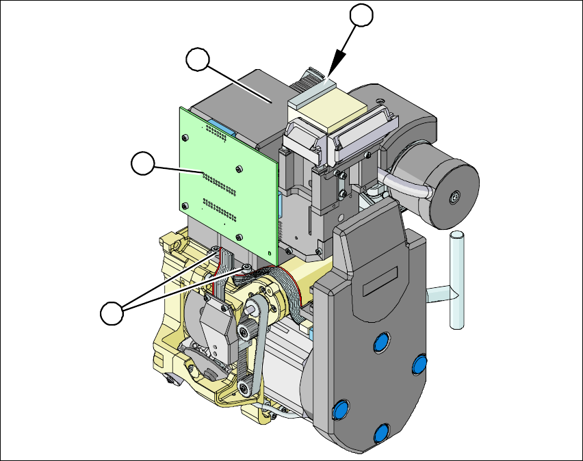
3.6.2 Installing / Removing the Component Camera
Fig. 24 Installing /removing the component camera
Æ Loosen the flat ribbon cable and strain reliefs, where necessary, so that the component camera
can be accessed.
2
3
3
1
Assembly Instructions 01005-Packet
Edition 12/2007
47
Æ Remove the ribbon cable plug from the socket on the "component illumination control" board
(1).
Æ Undo the four screws (3) holding the component camera.
Æ Carefully lift off the component camera (2).
Æ Make sure that all support surfaces are clean.
Æ Place the drillings in the new high-resolution camera on the parallel pins.
Æ Carefully place the camera onto the Collect&Place head until the camera socket rests evenly
on the support surfaces of the front part of the Collect&Place head.
Æ Fix the camera in place with the four screws provided (3).
Æ Connect the ribbon cable to the socket on the "component illumination board" (2).
Æ Reconnect the flat ribbon cable and strain reliefs.
Æ Ensure that all cables are fixed properly and are not exposed to any scouring or nudging during
movement of the axes.
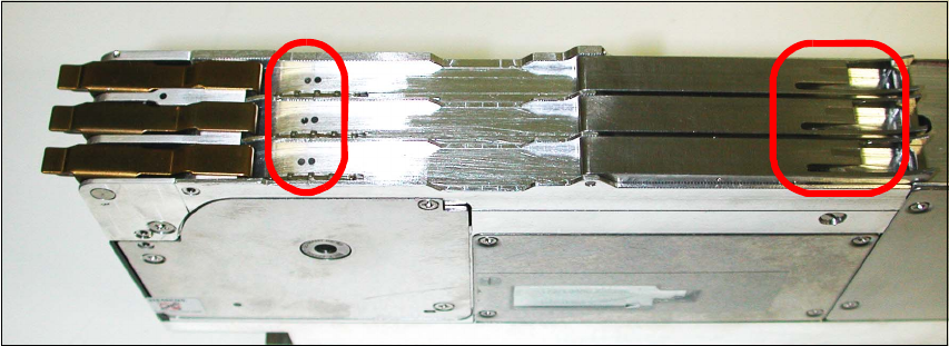
3.6.3 Tape Feeder 3x8mm S-Tape 01005 Component [00176100-xx]
The feeder is necessary to ensure optimal loading of all components.
You can differentiate this feeder from the previous ones by means of the two points (to the left in
the picture) and the additional nut (to the right in the picture). 3
Fig. 25 Tape feeder 3x8mm S-tape 01005 CO
3