00195398-0103-AI-01005Paket_DE_EN.pdf - 第54页
Asse mb ly In st ruct i on s 0100 5- Pac ket E di tio n 1 2 /20 07 54 3.6. 5.6 Final T e st of Changeover T able Height After fitt ing the ad justment sheet, check that the nozzle 905 does not collide with t he feed er c…
Assembly Instructions 01005-Packet
Edition 12/2007
53
3.6.5.5 Fitting the Adjustment Sheet
3
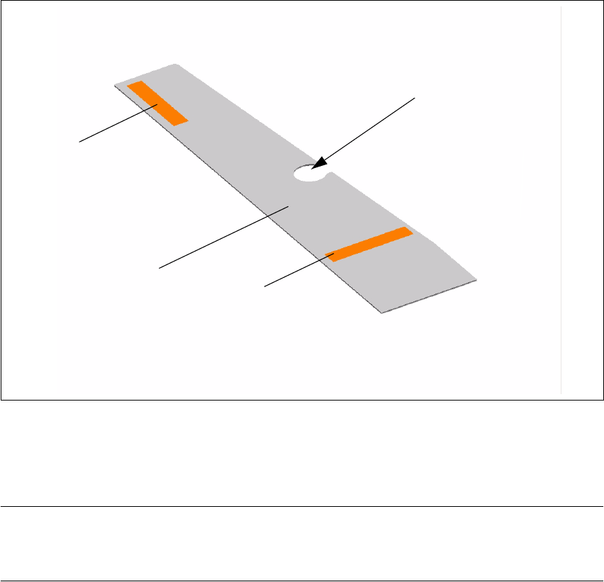
Fig. 30 Adjustment sheet
The adjustment sheets (1) have strips of adhesive tape (2) on both sides, so that they can be used
on both sides of the table contact surface. 3
NOTE:
Leave the cover sheet on the adhesive strips of the adjustment sheets until you have finished de-
termining the height. 3
Æ Remove the cover sheet from the adhesive strip (2) on the required side.
Æ Place the adjustment sheet (1) with the recess (3) over the ball calotte and attach the adjust-
ment sheet to the table contact surface.
Æ The adhesive strip which is still on the upper side of the adjustment sheet can be left there, as
the position of this cover sheet is outside the table contact surface.
2 3
1 3
2 3
3 3
Assembly Instructions 01005-Packet
Edition 12/2007
54
3.6.5.6 Final Test of Changeover Table Height
After fitting the adjustment sheet, check that the nozzle 905 does not collide with the feeder cover
flap. 3
Æ Carefully move the gantry (with the nozzle 905 in placement position) along the entire cover
flap area. The nozzle must not touch the flap.
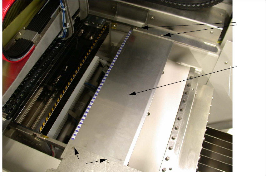
3.6.5.7 Fitting the Locking Plate (Feeder Cover Plate)
If the changeover table height has been calibrated, you will need to replace the locking plate (1).
Fig. 31 Dismantling the locking plate
Æ Loosen the 4 fastening screws (2) and remove the existing locking plate (1).
1 3
2 3
2 3
Assembly Instructions 01005-Packet
Edition 12/2007
55
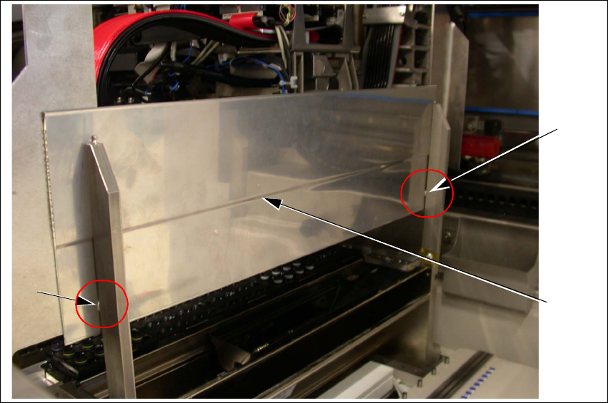
Fig. 32 Fitting a new locking plate
Æ Fit the new locking plate with both washers (1). The curvature (2) is on the underside as shown
in Fig. 32.
Æ Clean the contact surface with alcohol and attach the track scales according to the previous
allocation and measurements.
3.6.5.8 Final Test of Changeover Table Height
After fitting the adjustment sheet, check that the nozzle 905 does not collide with the locking
plate. 3
Æ Carefully move the gantry (with the nozzle 905 in placement position) along the entire locking
plate area. The nozzle must not touch it.
Æ Adjust the locking plate fixtures if necessary.
1
1
2