00195398-0103-AI-01005Paket_DE_EN.pdf - 第48页
Asse mb ly In st ruct i on s 0100 5- Pac ket E di tio n 1 2 /20 07 48 3.6. 4 Insert ing th e Sleeve SP12 Com p. / 270 D egre e Part ition [ 0305 4107- xx] The slee ves have a 270 d egree partition an d are designated wit…
Assembly Instructions 01005-Packet
Edition 12/2007
47
Æ Remove the ribbon cable plug from the socket on the "component illumination control" board
(1).
Æ Undo the four screws (3) holding the component camera.
Æ Carefully lift off the component camera (2).
Æ Make sure that all support surfaces are clean.
Æ Place the drillings in the new high-resolution camera on the parallel pins.
Æ Carefully place the camera onto the Collect&Place head until the camera socket rests evenly
on the support surfaces of the front part of the Collect&Place head.
Æ Fix the camera in place with the four screws provided (3).
Æ Connect the ribbon cable to the socket on the "component illumination board" (2).
Æ Reconnect the flat ribbon cable and strain reliefs.
Æ Ensure that all cables are fixed properly and are not exposed to any scouring or nudging during
movement of the axes.
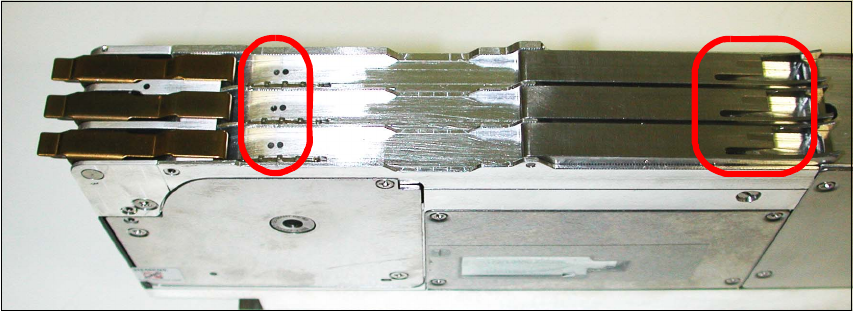
3.6.3 Tape Feeder 3x8mm S-Tape 01005 Component [00176100-xx]
The feeder is necessary to ensure optimal loading of all components.
You can differentiate this feeder from the previous ones by means of the two points (to the left in
the picture) and the additional nut (to the right in the picture). 3
Fig. 25 Tape feeder 3x8mm S-tape 01005 CO
3
Assembly Instructions 01005-Packet
Edition 12/2007
48
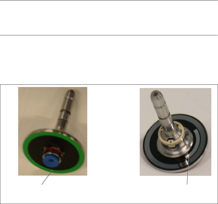
3.6.4 Inserting the Sleeve SP12 Comp. / 270 Degree Partition [03054107-xx]
The sleeves have a 270 degree partition and are designated with a green color ring. Each sleeve
can be identified by its unique serial number. 3
NOTE:
The sleeves must always be inserted into the same segment at the placement head in which they
were measured. Document this association (sleeve serial number with segment number) in the
machine log. 3
The "sleeve SP12 comp. / 270 degree partition" may only be used for the 01005 components with
the travel profiles 33/34 and 35. Otherwise the soft sleeve spring might cause the premature blow
off of the components. During the placement of larger component shapes, loss of placement
throughput may also occur. 3
Fig. 26 Sleeve SP12 comp. / 270 degree partition
Green color ring
270 degree partition
Assembly Instructions 01005-Packet
Edition 12/2007
49
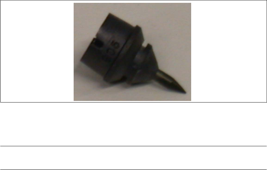
3.6.4.1 Nozzle, type 905 ESD / 1 x 0.15 [03057320-xx]
Æ Clean the nozzles daily to avoid pickup and centering errors.
3
Fig. 27 Nozzle, type 905 ESD / 1 x 0.15
3.6.5 Calibration of Changeover Table Height for SIPLACE D4
NOTE:
These settings only need to be performed for SIPLACE D4 machines. 3
3.6.5.1 Purpose
To measure the tape pockets of 01005 components, with the PCB camera, you need an optimum
focal position. This focal position is achieved by calibrating the height of the changeover table. A
correction height is determined for the changeover table at each location. 3
Depending on the height situation at a location, you will need to place small adjustment sheets
with a thickness of 0.5 and/or 1.0 mm between the changeover table support and the table itself.
These adjustment sheets are not specific to a particular changeover table and can remain at the
machine. 3
3.6.5.2 Determining the Changeover Table Height
To determine the required thickness of the adjustment sheet, move the Z-axis with the nozzle 901/
925 to the upper edge of the changeover table measuring gauge. The Z height is then read out
with the help of the CACCIA program. 3
Æ Attach "nozzle 901/925" to segment 1.
Æ In SITEST, start the function "Perform Head Reference Run". The Z-axis will be in the place-
ment position.
Æ Place the changeover table measuring gauge on track 1 of the changeover table.