00195398-0103-AI-01005Paket_DE_EN.pdf - 第55页
Asse mb ly In st ruct i on s 0100 5- Pac ket Edi t io n 12 /200 7 55 F ig . 3 2 Fi tti ng a ne w lo c ki ng pl at e Æ F it the new locking p late with both washers (1) . The curvatu re (2) is on the undersid e as sh own …
Assembly Instructions 01005-Packet
Edition 12/2007
54
3.6.5.6 Final Test of Changeover Table Height
After fitting the adjustment sheet, check that the nozzle 905 does not collide with the feeder cover
flap. 3
Æ Carefully move the gantry (with the nozzle 905 in placement position) along the entire cover
flap area. The nozzle must not touch the flap.
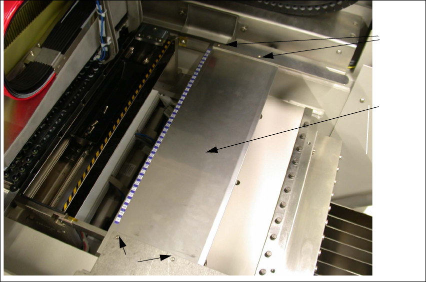
3.6.5.7 Fitting the Locking Plate (Feeder Cover Plate)
If the changeover table height has been calibrated, you will need to replace the locking plate (1).
Fig. 31 Dismantling the locking plate
Æ Loosen the 4 fastening screws (2) and remove the existing locking plate (1).
1 3
2 3
2 3
Assembly Instructions 01005-Packet
Edition 12/2007
55
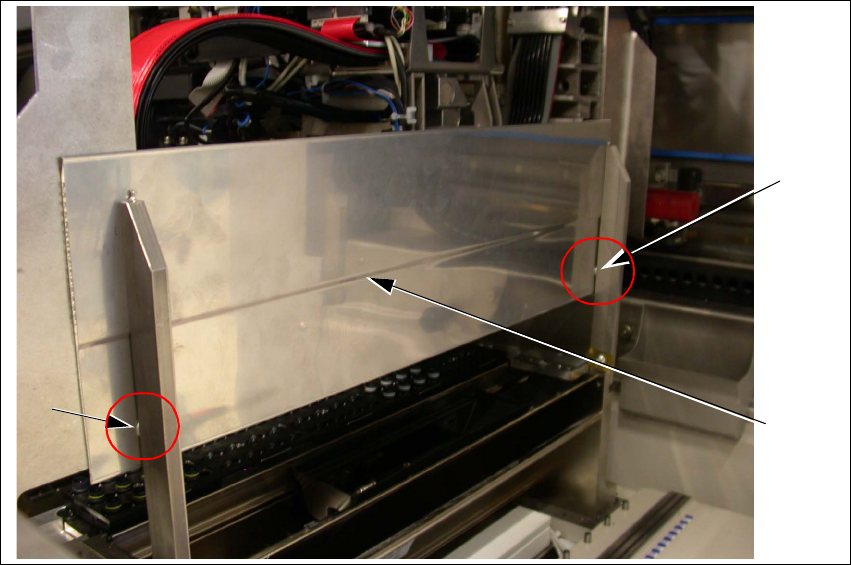
Fig. 32 Fitting a new locking plate
Æ Fit the new locking plate with both washers (1). The curvature (2) is on the underside as shown
in Fig. 32.
Æ Clean the contact surface with alcohol and attach the track scales according to the previous
allocation and measurements.
3.6.5.8 Final Test of Changeover Table Height
After fitting the adjustment sheet, check that the nozzle 905 does not collide with the locking
plate. 3
Æ Carefully move the gantry (with the nozzle 905 in placement position) along the entire locking
plate area. The nozzle must not touch it.
Æ Adjust the locking plate fixtures if necessary.
1
1
2
Assembly Instructions 01005-Packet
Edition 12/2007
56
3.6.6 Measuring the Component Camera and the Placement Head
DANGER
There is a high risk of accidents when working with the SITEST program.
SITEST may only be started by authorized persons, who have been specially trained by SIPLACE !
En
sure that all Component changeover tables (Component trolleys) are moved into the machine,
properly docked into place and configured (set up). 3
Æ Start the SITEST software.
Æ Configure the new camera in SITEST.
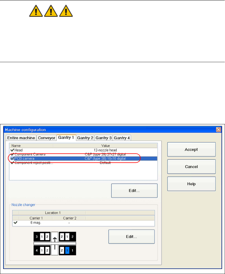
Æ Go to the main view and open the "Machine configuration" function.
Æ Choose the tab for the appropriate gantry (e.g. "Gantry 1) and activate the component camera
"C&P (Type 38) 16x16 digital".
Fig. 33 SITEST "configuring the Component camera"
Æ Perform a reboot and restart SITEST.
Æ Insert the new sleeves (refer to „Inserting the Sleeve SP12 Comp. / 270 Degree Partition
[03054107-xx]“ auf Seite 48).
Æ Perform a complete reference run for the machine.