00195398-0103-AI-01005Paket_DE_EN.pdf - 第57页
Asse mb ly In st ruct i on s 0100 5- Pac ket Edi t io n 12 /200 7 57 Æ S elect the function "C&P Heads ". Æ S elect the "Head and Compone nt Camera" function for the relevant placemen t head. Fig.…
Assembly Instructions 01005-Packet
Edition 12/2007
56
3.6.6 Measuring the Component Camera and the Placement Head
DANGER
There is a high risk of accidents when working with the SITEST program.
SITEST may only be started by authorized persons, who have been specially trained by SIPLACE !
En
sure that all Component changeover tables (Component trolleys) are moved into the machine,
properly docked into place and configured (set up). 3
Æ Start the SITEST software.
Æ Configure the new camera in SITEST.
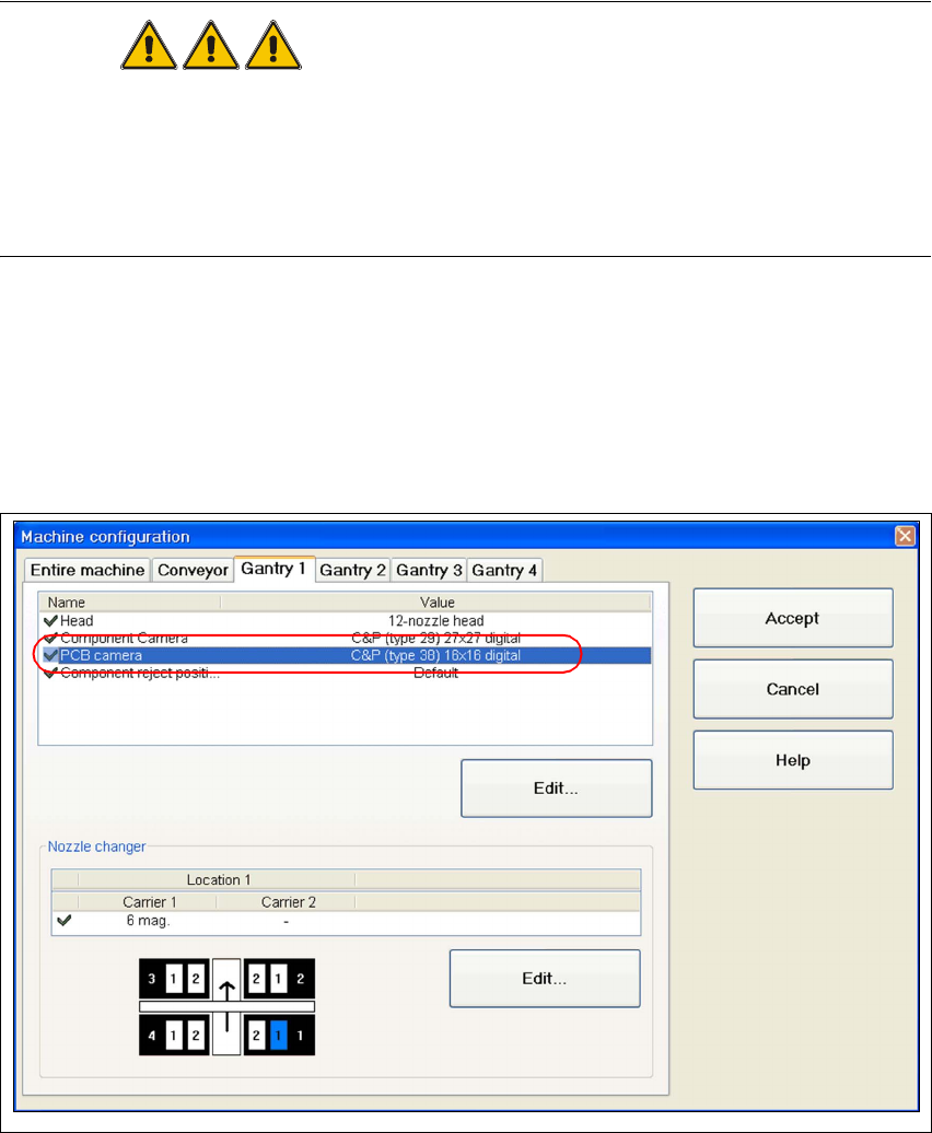
Æ Go to the main view and open the "Machine configuration" function.
Æ Choose the tab for the appropriate gantry (e.g. "Gantry 1) and activate the component camera
"C&P (Type 38) 16x16 digital".
Fig. 33 SITEST "configuring the Component camera"
Æ Perform a reboot and restart SITEST.
Æ Insert the new sleeves (refer to „Inserting the Sleeve SP12 Comp. / 270 Degree Partition
[03054107-xx]“ auf Seite 48).
Æ Perform a complete reference run for the machine.
Assembly Instructions 01005-Packet
Edition 12/2007
57
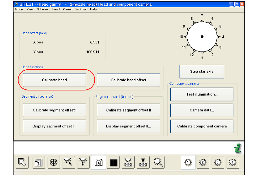
Æ Select the function "C&P Heads".
Æ Select the "Head and Component Camera" function for the relevant placement head.
Fig. 34 SITEST "head and component camera"
Æ Activate the "Calibrate head" function. A complete calibration of the head and the component
camera will be executed.
Æ Calibrate the machine zero point.
3.6.7 MFU with Retrofitted Machine using the 01005 Travel Profile 33/34
Æ
Check that the 3 sleeves for 01005 placement have been used at the measured positions.
Where necessary, insert the sleeves for 01005 placement. See also section 3.6.4 on page -
48.
Æ Make sure that the travel profiles in the CS description of the "Ceram Pad" component are set
according to the description in section 3.7.2.2 on page - 62.
Æ Perform the MFU with all segments i.e. also with the standard sleeves (at the same time).

Assembly Instructions 01005-Packet
Edition 12/2007
58
3.6.8 Costumer requires MFU using customer-owned 01005 components
This measurement can be performed when required by the customer. A MFU with 01005 compo-
nents can only count as a test for the placement capability of the components. 3
In no way should a measured offset be entered into a
FK_Off.ma during this process. 3
NOTE:
The proof for the machine capability is executed using the default components, i.e. "Ceram Pads
2x2mm taped" (00359505-01). 3
3.7 Configurations in SIPLACE Pro
3.7.1 Configuring the Setup
During setup and, if applicable, during the 0201-placement of the component sensor, the new
component camera must be entered. 3
Æ Open the required setup in SIPLACE Pro.
Æ Select the "Head" tab.