00195398-0103-AI-01005Paket_DE_EN.pdf - 第66页
Asse mb ly In st ruct i on s 0100 5- Pac ket E di tio n 1 2 /20 07 66 3. 8 Config urations at t he S t ation Sof tware 3.8. 1 Enabling Feeder Posi tion Reco gnitio n NOTE: The f eeder position recognition option must be …
Assembly Instructions 01005-Packet
Edition 12/2007
65
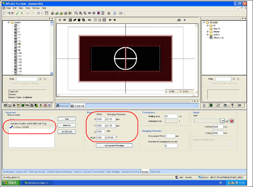
3.7.2.5 Assigning the Feeder
Æ Select the "Feeder" tab.
Æ Use the "Add" button to select the feeder type "3 x 8mm S 01005" from the feeder type list.
Æ Check the values for packing tolerance (+/- 0,1 mm) and angle (15°).
Fig. 41 SIPLACE Pro "component shape editor" - "feeder" tab
Assembly Instructions 01005-Packet
Edition 12/2007
66
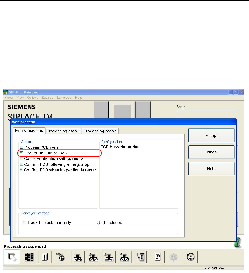
3.8 Configurations at the Station Software
3.8.1 Enabling Feeder Position Recognition
NOTE:
The feeder position recognition option must be enabled for placement with 01005 components. If
this is not the case, component pickup reliability may suffer.
Feeder position recognition can only be enabled or disabled from users with operating level ’Line
Engineer’ or higher. 3
Æ Select the function "Machine Options" from the main view of the station software.
Æ Select the "Entire Machine" tab.
Fig. 42 Stations software "machine options - entire machine"
Æ Enable the checkbox "Feeder Position Recognition".
Æ Confirm with "Accept".
Assembly Instructions 01005-Packet
Edition 12/2007
67
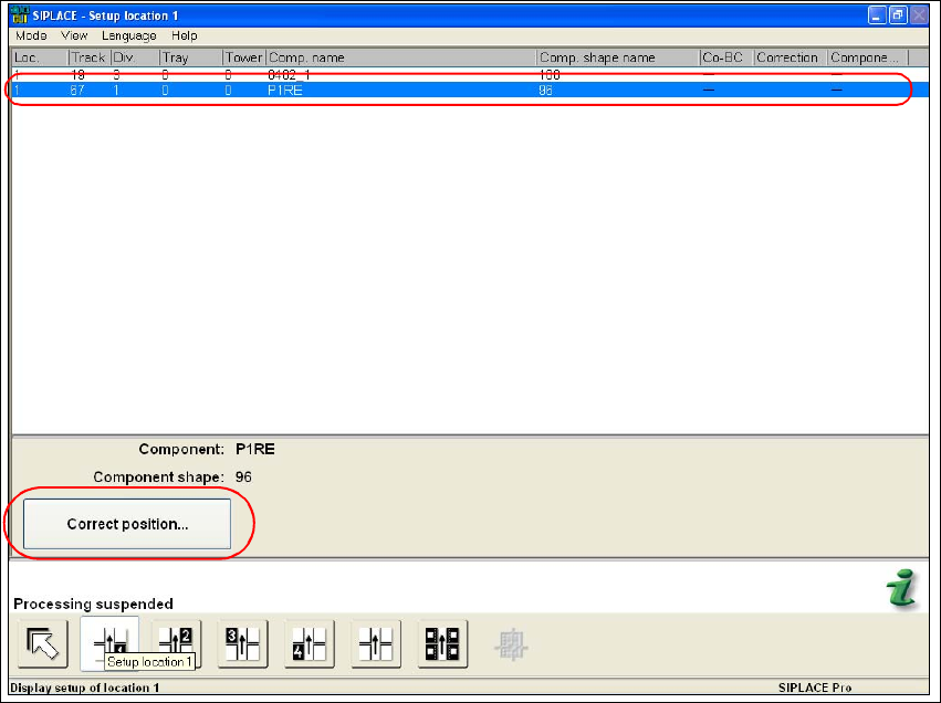
3.9 Final Tasks and Verification
3.9.1 Verifiying the Calculated Pickup Position at the Station
Æ Stop the placement process.
Æ Select the "Setup location" function in the main view of the stations software.
Æ Highlight in the list the feeder with the desired component.
Fig. 43 Stations software "Setup Location"
Æ Execute the "Correct position..." function.