SA_HF_intern_0194307-02_eng.pdf - 第17页
SIPL ACE HF-Ser ies Replacing the Gantry [030 06781-xx ] Serv ice Gan tri es 3 Copy ri ght © 200 4 S ie m ens 0019 43 07- 02 Is su e 1 1/ 2004 3-3 2 1 Unplug the p roximity switc h cable (2) and pull it forwards , out …
3
Service
Gantries
SIPLACE HF-Series
Replacing the Gantry [03006781-xx]
3-2
00194307-02 Issue 11/2004 Copyright © 2004 Siemens
5
5
6
1 4
3
2
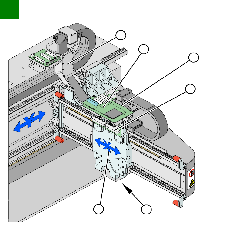
1. X-drive (primary) with head mount
2. X-mount with trailing cable
3. Head adapter board
4. Mount with PCB camera
5. Head board
6. Trailing cable console
Dismantle the placement head.
Remove the head adapter board (3). The x-mount fixtures are
now (2) accessible.
Unplug the following cables from the head board (5) and
remove them from the x-mount (2):
X motor cable
X-axis scanner head
Temperature sensor (if supplied).
SIPLACE HF-Series
Replacing the Gantry [03006781-xx]
Service
Gantries
3
Copyright © 2004 Siemens 00194307-02 Issue 11/2004 3-3
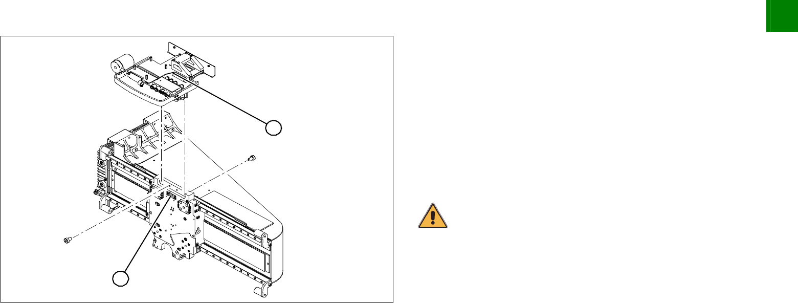
2
1
Unplug the proximity switch cable (2) and pull it forwards, out of
the head mount.
Undo the 8 screws (4 x at front/ 4x at back) fastening the x-
mount (1) and pull these up and out, together with the trailing
cable.
Loosen the two trailing cable pressure plates on the X gantry .
Remove the trailing cable as far as the trailing cable console.
Fasten the x-mount at a suitable point.
CAUTION
Make sure that the flat ribbon cable and the pneumatic hoses are not
rubbed against any parts or kinked. Watch out for sharp edges.
3
Service
Gantries
SIPLACE HF-Series
Replacing the Gantry [03006781-xx]
3-4
00194307-02 Issue 11/2004 Copyright © 2004 Siemens
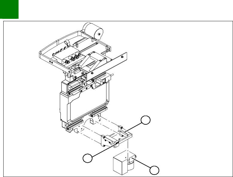
1
3
2
Undo the 4 screws fastening the PCB camera mount (1).
Remove the complete unit, including PCB camera (3) and
damping bracket (2).
Remove the connection cable fixtures from the gantry.
For strain-relief purposes, fix the mount (1) to a suitable place.
Take care not to damage the camera.