SA_HF_intern_0194307-02_eng.pdf - 第27页
SIPL ACE HF-Ser ies Replacing the T railing Cable [03013940 -xx] Serv ice Gan tri es 3 Copy ri ght © 200 4 S ie m ens 0019 43 07- 02 Is su e 1 1/ 2004 3-13 Overview 5 5 6 7 1 4 3 2 The flat ribbon cables a re r un from…

3
Service
Gantries
SIPLACE HF-Series
Replacing the Trailing Cable [03013940-xx]
3-12
00194307-02 Issue 11/2004 Copyright © 2004 Siemens
3.1.2 Replacing the Trailing Cable [03013940-xx]
Parts
Trailing cable for HF 3 (gantry 1 or 3) [03013642-xx]
Trailing cable for HF (gantry 4) [03013940-xx]
Preparation
The trailing cable is supplied as a fully assembled module. Depending upon the configuration of the machine, you will
need to remove the relevant modules, covers and cover plates before you can dismantle the trailing cable.
Where necessary, remove the cover plates from the gantry
trailing cable. Mark their exact position to ensure correct
replacement later.
Remove the top central cover from the SIPLACE machine.
Remove the top EMC plate.
Remove the upright EMC plates so that you can reach the
trailing cable.
SIPLACE HF-Series
Replacing the Trailing Cable [03013940-xx]
Service
Gantries
3
Copyright © 2004 Siemens 00194307-02 Issue 11/2004 3-13
Overview
5
5
6
7
1
4
3
2
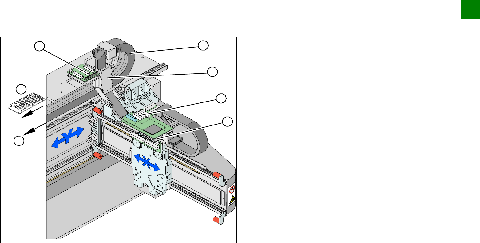
The flat ribbon cables are run from the head board (1), via
the trailing cable console (2) and the power track chain (3)
to the gantry interface (7) and the trailing unit interface
gantry (4).
The compressed air hoses are run from the pneumatic
distributor (6), via the trailing cable console (2) and the
power track chain (3) to the gantry distributor (5) .
3
Service
Gantries
SIPLACE HF-Series
Replacing the Trailing Cable [03013940-xx]
3-14
00194307-02 Issue 11/2004 Copyright © 2004 Siemens
Disassembly
3
3
4
5
1
2
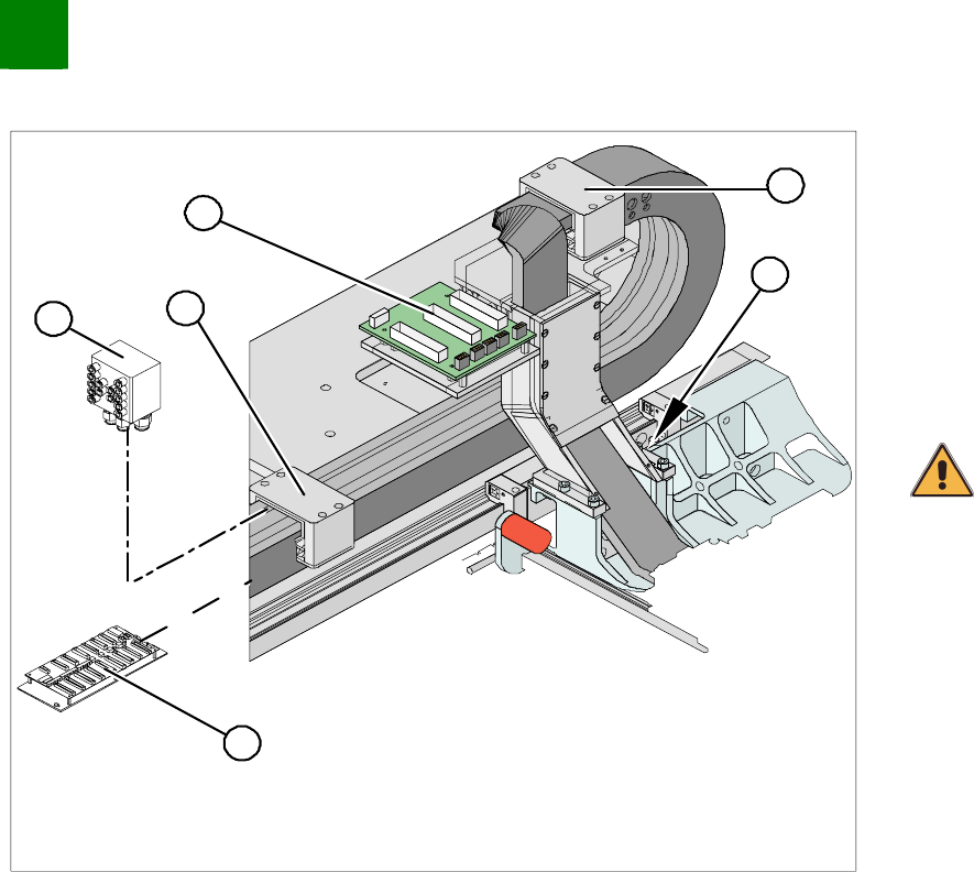
Disconnect the flat ribbon cable from the trailing unit interface
gantry (1). Take care not to lose the brackets for the plug-and-
socket connections. They could fall out and be lost.
Remove cable ties where necessary.
Remove the cover from the gantry distributor (5).
Undo the screws fastening the gantry distributor (5).
Remove all compressed air hoses from the gantry distributor.
CAUTION
Note the order in which the terminal connections are arranged. You
will need this sequence later, for reassembly purposes.
NOTE
Now reconnect the gantry distributor to the new trailing cable and
install the distributor in the machine..
Secure the end of the trailing cable (with cable ties) in the
machine to prevent it hanging loosely and damaging other
machine components.