SA_HF_intern_0194307-02_eng.pdf - 第59页
SIPL ACE HF-Ser ies Replacing the Cu tter Blades [03009259 - xx] Serv ice Cu tter 3 Copy ri ght © 200 4 S ie m ens 0019 43 07- 02 Is su e 1 1/ 2004 3-45 WARNING There is a high risk of inju ry from the bl ades and the ta…

3
Service
Cutter
SIPLACE HF-Series
Replacing the Cutter Blades [03009259-xx]
3-44
00194307-02 Issue 11/2004 Copyright © 2004 Siemens
3.2 Cutter
See
Safety Instructions for Work on the Cutting Device:
Page 2-2
3.2.1 Replacing the Cutter Blades [03009259-xx]
Parts
The article number of the cutter blades may vary according to the cutter version and function status.
Pneumatic cutter Function status Cutter blades, attuned
03000487 -01 to -03 03000501-xx
03000487 -04 to -05 03009259-xx
03019941 -01 03009259-xx
Tools
Thick protective gloves
Assembly plate [00312731-xx]
Alternatively: 2 large parallel clamps and a stabile table with even surface to clamp down the dismantled cutter.
SIPLACE HF-Series
Replacing the Cutter Blades [03009259-xx]
Service
Cutter
3
Copyright © 2004 Siemens 00194307-02 Issue 11/2004 3-45
WARNING
There is a high risk of injury from the blades and the tape deflector.
Wear appropriately thick protective gloves!
Never reach into the cutter from below or into the empty-tape duct from above.
Make sure that no-one can injure themselves on the cutter after it has been dismantled and placed next to the
machine!
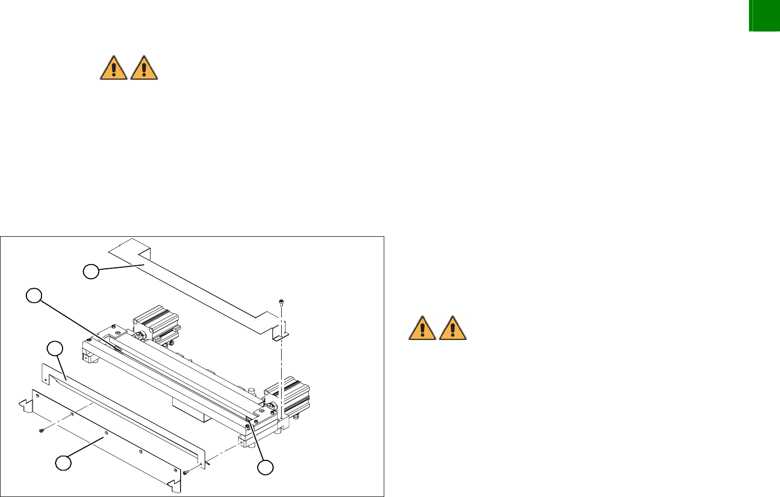
Disassembly
4
1
4
3
2
Dismantle the component trolley feed device and the cutter.
Remove the protective sheet (2) and the deflector plate (3).
Remove the cover plate (1).
Remove the caps (4) on the fastening screws.
WARNING
There is a risk of injuring yourself on the cutting edge of the blades.
For all further work, either fix the cutter to the assembly plate
with 4 hexagon socket-head screws or use screw clamps to
fasten the cutter to a sturdy, stabile table.
3
Service
Cutter
SIPLACE HF-Series
Replacing the Cutter Blades [03009259-xx]
3-46
00194307-02 Issue 11/2004 Copyright © 2004 Siemens
4
3
5
1
4
3
2
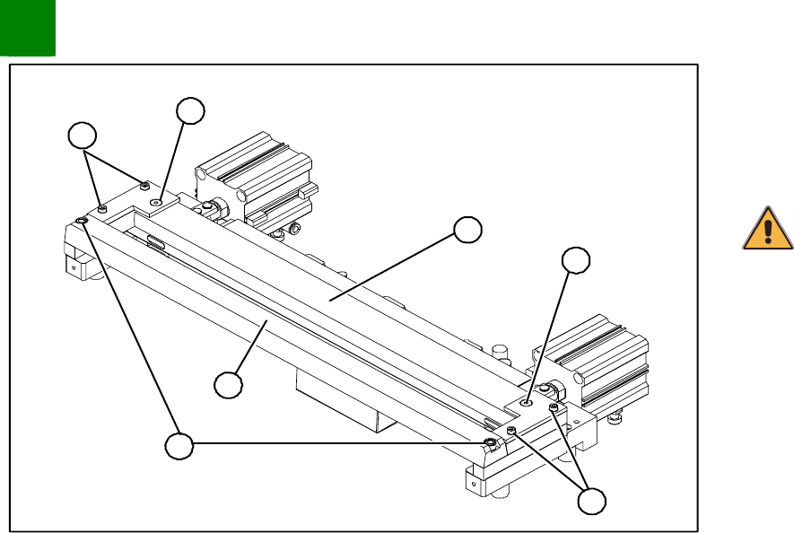
Loosen and remove the two screws (1) fastening the stationary
blade (2).
Undo the screws fastening the left and right tape deflectors (3)
above the moveable blade.
CAUTION
Do not loosen the two Phillips screws (4)
Remove the tape deflector holder with the tape deflector (5) and
carefully place the whole unit down (with the tape deflector
facing upwards).