SA_HF_intern_0194307-02_eng.pdf - 第62页
3 Serv ice Cu tter SIPL ACE HF-Ser ies Replacing the Cu tter Blades [03009259 - xx] 3-48 0019 43 07- 02 Is su e 1 1/ 2004 Copy ri gh t © 2 004 S ie m ens If the new blades are no t clean, careful ly r ub t hem (wear p …
SIPLACE HF-Series
Replacing the Cutter Blades [03009259-xx]
Service
Cutter
3
Copyright © 2004 Siemens 00194307-02 Issue 11/2004 3-47
3
4
1
5
4
3
2
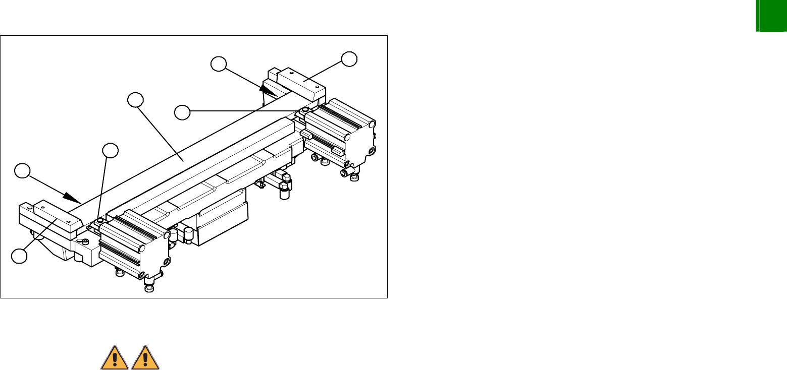
Remove the right-hand holding-down device (1) and the left
holding-down device (2), plus the spacers below.
Use an SW 10 open-ended wrench to push against the joint (3),
while loosening the hexagon socket-head screw of the joint (4)
in the moveable blade. This may require more strength than
usual as the screws have been secured with Loctite no. 243.
Grasp both ends of the moveable blade (5) with the protective
gloves and pull it upwards and out.
Installation – Requirements
WARNING
There is a high risk of injury from the blades and the tape deflector.
Wear appropriately thick protective gloves!
Make sure all parts are clean before installing them.
The new blades are covered with a fine lubrication film. Do not use fat dissolving agents on the blades (risk of rust
film forming) or apply any additional lubrication (risk of contamination by particles sticking to the blades). This
would only impair the movement of the moveable blade.
3
Service
Cutter
SIPLACE HF-Series
Replacing the Cutter Blades [03009259-xx]
3-48
00194307-02 Issue 11/2004 Copyright © 2004 Siemens
If the new blades are not clean, carefully rub them (wear protective gloves) with a well folded, clean and dry cloth.
Do not use fat dissolving agents!
Preparation
1
6
5
4
3
2
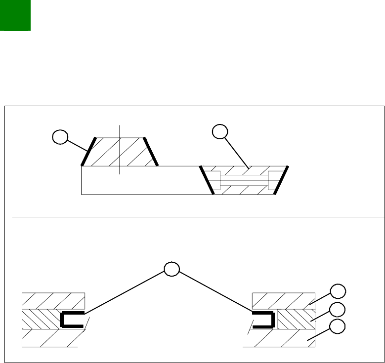
Make sure the cutter is in the correct rotary position (see the
slant of the blade).
Check the positioning of the individual blades to one another.
Before installation, lubricate the sliding surface of the moveable
blade.
1. Stationary blade
2. Moveable blade
3. Sliding surfaces to be lubricated
4. Holding-down device
5. Spacer
6. Contact surface
SIPLACE HF-Series
Replacing the Cutter Blades [03009259-xx]
Service
Cutter
3
Copyright © 2004 Siemens 00194307-02 Issue 11/2004 3-49
Installation
2
3
4
1
4
3
2
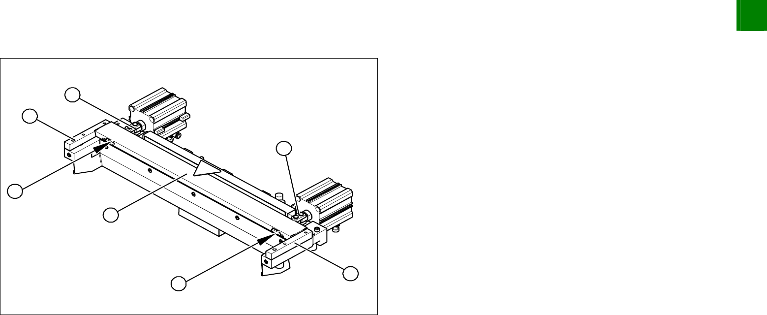
Correctly insert the moveable blade (1) into the cutter and shift
it along to its original installation position.
Apply Loctite no. 243 to the two M4 screws, to fasten the joint in
the moveable blade.
Insert the screws (2) into the left and right holes provided in the
moveable blade.
NOTE:
Make sure that the joint (3) can slide into the slot (= anti-twist
function) in the moveable blade without obstruction.
Use an SW 10 open-ended wrench to push against the relevant
joint(3) and then tighten both screws (2) to a torque of 2. – 3. N.
Replace the two covers (caps).
Place the two new spacers (4) to the left and right of the
moveable blade. The spacer side marked with a number must
face towards the blade.
The spacers and blades are matched !